What is the PI protective film process for rigid-flex PCBs?


Rigid-flex printed circuit boards (R-FPCBs) are composite boards formed by pressing rigid and flexible layers together, combining the characteristics of both.
With the advancement of the printed circuit board (PCB) industry, R-FPCBs—as a vital component of PCBs—have seen growing demand due to their high performance, integration capabilities, and versatility in three-dimensional assembly.
With the rapid advancement of R-FPCB technology, customer expectations for surface aesthetics continue to rise.
Currently, during R-FPCB production, the flexible panel surface frequently exhibits cosmetic defects, including pitting, prepreg powder residue, resin overflow, compression cracking, and contamination, leading to high scrap rates.
Common cosmetic defects are as follows:
| Defect Type | Primary Root Causes | Why It Occurs Mainly in the Flexible Area |
|---|---|---|
Pitting | • Uneven resin flow during lamination • Resin starvation or micro-void formation • Moisture outgassing from PI or adhesive • Over-etching of thin copper | • PI lacks resin buffering capacity of FR-4 • Thin copper exaggerates surface roughness • High pressure squeezes resin away from flex zones |
Prepreg Powder | • Glass fiber dust from prepreg cutting and lay-up • Resin particle fallout during handling • Inadequate pre-lamination cleaning | • Flex areas are often window-opened • No solder mask or copper plane protection • PI film easily attracts static-borne particles |
Resin Overflow (Resin Bleed / Flash) | • Excessive lamination temperature and pressure • Poor resin flow control design • Lack of resin dams or stop-flow structures | • Flex openings act as low-resistance resin paths • PI and adhesives soften earlier than FR-4 • Thickness mismatch drives resin into thin zones |
Cracking | • CTE mismatch between FR-4, PI, copper, adhesive • Over-pressing during lamination • Residual stress released during bending or routing | • Flex copper is thin and under tensile stress • Resin-rich or resin-poor zones create stress points • Cracks propagate easily along copper grain |
Contamination (Stains, Smudges, Foreign Matter) | • Chemical residue from desmear, etching, plating • Adhesive low-molecular bleed-out • Handling contamination (dust, fingerprints) | • PI has higher surface energy and attracts residues • No solder mask isolation • Flex areas are frequently exposed and handled |
General Cosmetic Degradation | • Lamination parameters optimized for rigid boards • Poor moisture control of PI and prepreg • Inadequate flex-area masking and protection | • Flexible zones are process-incompatible with rigid PCB flow • Extreme thickness discontinuity concentrates stress |
This paper investigates the manufacturing process of polyimide (PI) protective films and the structure of R-FPCBs to identify a production method that can mitigate these cosmetic defects.
Solution Design
Development Approach
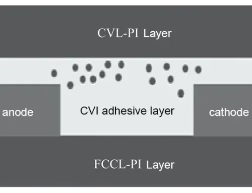
A PI protective film is applied to the surface of the cover film in the flexible area. This film blocks prepreg powder and resin overflow, protects the flexible area from compression damage and chemical contamination, and is removed along with the cover film during lamination. The PI protective film is incorporated into the R-FPCB laminate structure, as illustrated in Figure 1. For multi-layer flexible structures, the PI protective film is applied only to the outermost flexible layer.

Figure 1. Fabrication of R-FPCB stack using PI protective film.
Experimental Design
› Phase 1 Process Research
(1) Alignment Mark Lines for PI Protective Film Application
When applying the PI protective film to the cover film surface, design PI protective film etching alignment mark lines on the flexible layer (matching the cover film mark lines). These mark lines serve for alignment during PI protective film lamination and for detecting misalignment.
(2) Optimized PI Film Application Area for Lamination
Design the PI protective film application area 0.3mm smaller on each side than the flexible region to prevent lamination overlap into the rigid area.
(3) PI Film Application Methods and Evaluation
Three PI film application methods exist: pre-browning application, pre-browning application + rapid pressing of PI film, and post-browning application.
The pre-browning application must be tested for potential issues such as PI film detachment during browning, chemical solution seepage, or residue.
Results will determine whether to adopt the post-browning application process.
(4) Ease of PI Protective Film Application and Bonding
As the PI protective film is a low-viscosity material, verify its ease of application during lamination. Use a heating pad during operation and confirm whether it detaches easily after bonding.
(5) PP Processing and Groove Design for Rigid-Flex Boards
The PP near the PI protective film does not require full milling or inward retraction. Utilize PP to fill height differences between rigid and flexible zones. Only mechanically mill a groove along the rigid-flex edge to facilitate subsequent cover opening. Additionally, when milling PP for rivet holes, drill holes to facilitate rivet positioning.
(6) PI Protective Film Removal and Inspection
After opening the cover, simultaneously peel off the PI protective film. Verify whether the film peels off easily and whether issues like adhesive residue or peeling occur.
(7) Inspection for Missed PI Film Application or Removal
After applying and removing the PI protective film, respectively, verify whether any missed application or removal occurs and whether such defects can be visually identified.
(8) Large-Cavity Cover Design for PI Film Testing
The test board employs a large-cavity thin cover design to facilitate more intuitive verification of PI protective film performance.
(9) Testing Single- and Multi-Layer Flexible Boards with Laser-Milled Contours
Test both single-layer flexible boards and multi-layer flexible boards with pre-laser-milled contours to determine applicability, which will define the scope of subsequent specifications.
(10) All other components remain unchanged from the original R-FPCB design.
Process Research is as follows:
| No. | Process Study | Result |
|---|---|---|
| 1 | Apply PI Film | Apply PI film along the etched marking line on the flexible board surface, and laminate it onto the coverlay. |
| 2 | Ease of Identifying Missed Application | The applied PI film has a reflective golden surface that is clearly distinguishable from areas without PI film, making it convenient to check for missed application. |
| 3 | Heat Fixation | After lamination, heating with a hot press pad is required to enhance adhesion and fixation. Temperature: (80 ± 5) °C. |
| 4 | Apply Before Brown Oxidation | (1) During the brown oxidation line process, PI film lifting occurred, and edge warping was also observed, resulting in unstable adhesion. (2) Due to weak adhesion, even if the film does not fall off after brown oxidation, chemical solution seepage still occurs. After removing the PI film, obvious chemical stains and residue are observed. |
| 5 | Apply Before Brown Oxidation + Quick Press PI Film | After applying PI film and performing one additional quick press, the PI film adheres closely to the flexible board. However, due to the thin adhesive layer of the PI film, insufficient pressure occurs in the middle of dense circuit areas, and solution seepage still occurs during brown oxidation. |
| 6 | Apply After Brown Oxidation | Although it is a low-adhesion material, it has a certain electrostatic adsorption effect. After lamination and heat fixation, it is not easy to peel off. |
| 7 | Whether Quick Press Is Needed | (1) After heat pad fixation, the PI film bonds well with the coverlay and is not easy to peel off. (2) Comparative tests were conducted between one-time quick press and no quick press. After coverlay opening, full inspection of the PI film protection area showed no PP powder, adhesive overflow, press marks, or contamination issues. There is no difference in effect between quick press and no quick press. |
| 8 | After Coverlay Opening | After opening, the PI film can be easily peeled off. Without damaging the PP in the non-etched flexible area, the PI film can be directly lifted and removed during opening. After opening, full inspection of the PI film protection area shows no PP powder, adhesive overflow, or scratch issues. |
| 9 | Large-Cavity Coverlay Design | Verification of PI film performance was conducted by increasing the size of large-cavity coverlay products. After opening, full inspection of the PI film protection area shows no PP powder, adhesive overflow, press marks, or contamination issues. |
| 10 | Multi-Panel Flexible Board Pre-Laser Cutting of Sharp Profile | Additional verification of the process combining pre-laser cutting of sharp profiles on multi-panel flexible boards with PI film application. After opening, full inspection of the PI film protection area shows no PP powder, adhesive overflow, press marks, or contamination issues. |
Table 1 Results of Process Study
› Phase II Material Comparison
Four materials from different suppliers were selected: BST-PI film, YZ-PI film, YH-PI film, and LH-PI film. Operational difficulty and cost comparisons were conducted.
› Acceptance Criteria
Acceptance criteria for PI protective film application on rigid-flex boards primarily involve visual inspection of the flexible area’s appearance. Under ideal conditions, the film is deemed acceptable if free of surface defects such as pitting, PP powder residue, adhesive overflow, or contamination.
Experimental Results and Analysis
Phase I Process Research
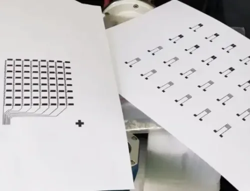
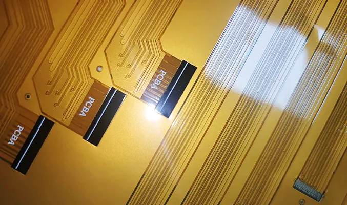
Process procedures and outcomes are detailed in Table and Figure 2.

Figure 2. Applying PI and opening the lid.
(1) Applying PI film before passivation, regardless of rapid pressing, carries a risk of chemical solution seepage after passivation and is therefore not feasible.
(2) Based on test results, combined with the material properties of the PI protective film and supplier recommendations, the post-passivation application process remains suitable for this material.
(3) Applying PI protective film to the flexible area effectively protects the flexible board surface and improves surface appearance issues.
Second-Stage Material Comparison
Usage details for the four PI films are shown in Table 2.
| No. | Material Vendor | Operation Difficulty |
|---|---|---|
| 1 | BST-PI Film | The PI film has high adhesion. If slightly misaligned during application, it is difficult to adjust, resulting in high operation difficulty. |
| 2 | YZ-PI Film | When the PI film is applied onto the coverlay, its adhesion is low. Even if misaligned, it is relatively easy to adjust. |
| 3 | YH-PI Film | After heating with a hot press pad, the PI film directly curls and shrinks. During heating, a certain amount of pressure must be applied simultaneously. Due to process limitations, testing results are judged as non-conforming. |
| 4 | LH-PI Film | When the PI film is applied onto the coverlay, its adhesion is relatively low, and if misaligned, it is easy to adjust. |
Table 2 PI Material Comparison
(1) BST-PI film and YH-PI film present high operational difficulty and are unsuitable for our company’s production conditions.
(2) LH-PI film and YZ-PI film demonstrate identical application performance and effectiveness, but LH-PI film offers a price advantage.
It is recommended to adopt the LH-PI film for use.
Conclusion
This study investigates the manufacturing process of PI protective films and the structure of R-FPCBs.
Apply the PI protective film to the surface of the cover film in the flexible area to block PP powder and adhesive overflow, protecting the flexible area from compression damage and chemical contamination.
When the cover is opened, remove the PI protective film simultaneously.
Process flow research, material testing from different manufacturers, and batch technical trial boards validated the findings from each stage.
The research indicates that the post-browning application process is most suitable for PI protective films, with LH-PI film demonstrating excellent performance and cost advantages.
Batch technical trial boards validated the PI film process’s stable operation and maturing performance.
It effectively improves surface appearance while resolving technical challenges like delamination, cracking, and adhesive overflow, significantly contributing to yield enhancement and defect reduction.
This research successfully established a manufacturing process integrating R-FPCBs with PI protective films.