Rigid Flex PCB Manufacturing: A Process Overview


Rigid Flex PCB Manufacturing: A Process Overview
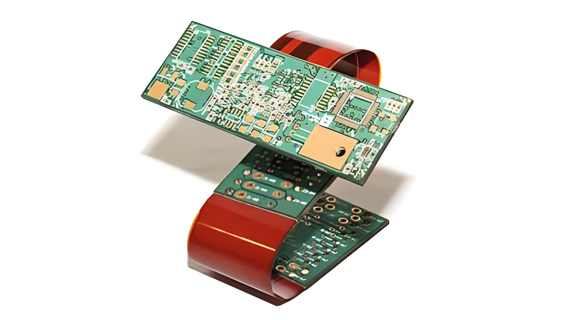
1. What is a Rigid Flex PCB?
A rigid flex PCB combines stiff board parts with flexible sections in one structure. This design removes connectors, which cause 82% of connection failures (IPC-2223 data). These rigid flex printed circuit boards excel in:
High-density packaging: 3D configurations reduce space by 60% vs. traditional PCBs
Extreme environments: Operate in harsh environments (-65°C to 260°C)
Dynamic flexing: Endure >500,000 bends in wearable flexible PCBs
2. Material Selection & Preparation
2.1 Core Materials Comparison
| Material | Type | Thickness | CTE (ppm/°C) | Key Use |
|---|---|---|---|---|
| Polyimide Film | Flex | 12-125μm | 15 | Aerospace rigid flex designs |
| FR4 | Rigid | 0.2-3.2mm | 13 | Rigid board base layers |
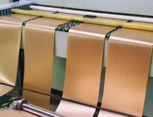
| RA Copper | Conductive | 9-70μm | 17 | Flexible sections requiring bends |
Critical Notes:
High volume production favors PET films for cost, but limits dynamic flex cycles
Copper layers in flex PCB design require rolled annealed (RA) foil for bend endurance
3. Rigid Flex PCB Manufacturing Process
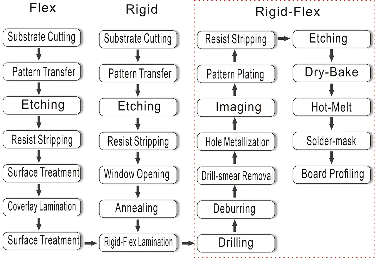
Rigid flex manufacturing process
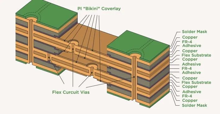
3.1 Layer Stackup Design
Advanced rigid flex circuits use asymmetric stacks:
Flexible and rigid zones: 2-6 polyimide layers sandwiched between FR4
Copper layers transition: Tapered copper at rigid-flex junctions prevents cracking
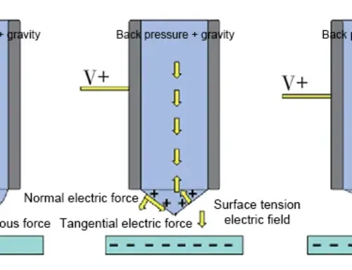
3.2 Imaging & Etching
Laser Direct Imaging (LDI): 25μm traces for flexible printed circuit boards
Plasma Etching: Ar/O₂ gas achieves 45° sidewall angles in flex material
3.3 Multilayer Lamination
| Step | Parameters | Purpose |
|---|---|---|
| Flex Prepreg Bonding | 180°C @ 300psi | Adhere the polyimide film to the cores |
| Rigid Layer Fusion | 220°C @ 500psi | Bond FR4 to flexible sections |
*CTE mismatch control: Δ<2ppm/°C between adjacent layers*
3.4 Drilling & Plating
Laser Drilling: <50μm microvias in rigid-flex PCB transition zones
Electroless Copper: 18-25μm deposition for reliable copper layers
3.5 Surface Finishing
| Finish | Cost | Bend Cycles | Applications |
|---|---|---|---|
| ENIG | $$$ | 200,000+ | Military flex rigid pcb |
| OSP | $ | 50,000 | Consumer flexible pcb |
4. Quality Control for Rigid Flex PCB Manufacturers
4.1 Electrical Testing
Impedance control: ±10% tolerance for high-speed rigid flex circuits
4-wire Kelvin testing: Detect <1mΩ resistance fluctuations
4.2 Mechanical Validation
Dynamic Flex Test: 6x board radius bends per IPC-2223C
Thermal shock: 100 cycles (-55°C↔125°C) for harsh environment validation
4.3 Certification Standards
Rigid flex PCB manufacturers must comply with:
UL 94V-0 flame rating
IPC-6013D Class 3
ISO 13485 for medical flex and rigid flex devices
Reference: PCB Testing: 8 Essential Methods for Quality Assurance (2025 Update)
5. Industry Innovations & Challenges
5.1 Technical Barriers
Z-axis expansion: 15ppm (PI) vs 13ppm (FR4) causes warpage in rigid flex pcb manufacturing process
Flex PCB design complexity: 8+ layer counts require 3D modeling tools
5.2 Cutting-Edge Solutions
Additive Manufacturing: Aerosol-jet printed copper layers on 3D surfaces
Adhesive-less FCCL: Eliminates 0.3mm glue layers in flexible and rigid interfaces
6. Choosing a Rigid Flex PCB Manufacturer
Key Selection Criteria:
High volume capability: >10,000 panels/month with ≤0.5% defect rate
Flex rigid PCB expertise: Minimum 5 years in mil-aero applications
Material mastery: Certified polyimide film suppliers (DuPont®/Panasonic®)
Pro Tip: Request 3D CT scans for rigid flex printed circuit boards with >16 layers.
Conclusion
Rigid Flexible PCB manufacturing, though complex, shares many conceptual similarities with rigid PCB production. By understanding each step, from stacking layers to final lamination and routing, engineers can create high-quality flexible circuits. You can tailor these circuits for many different applications. As technology improves, rigid-flexible PCBs will keep playing an important role in creating new electronic products.
FAQ:
1. What is a rigid flex PCB and why is it used?
A rigid flex PCB is a hybrid circuit board that combines rigid FR4 sections with flexible polyimide layers. This structure eliminates connectors—responsible for 82% of connection failures—and supports high-density 3D packaging, extreme temperature environments, and over 500,000 dynamic bend cycles.
2. What materials are commonly used in rigid flex PCB manufacturing?
Rigid flex PCBs typically use polyimide film for flexible zones, FR4 for rigid layers, and rolled annealed (RA) copper for conductive traces. RA copper is essential for bend durability, while polyimide provides heat resistance and stability across a wide temperature range.
3. How is a rigid flex PCB manufactured?
The process includes stackup design, laser imaging, plasma etching, multilayer lamination, microvia drilling, plating, and surface finishing. Advanced methods like Laser Direct Imaging (25 μm lines) and laser drilling (<50 μm microvias) ensure high precision, especially at rigid-flex transition zones.
4. What quality control tests are required for rigid flex PCBs?
Manufacturers use electrical impedance tests, 4-wire Kelvin resistance checks, dynamic bending tests, and thermal shock cycling. High-reliability industries require compliance with IPC-6013D Class 3, UL 94V-0, and ISO 13485 for medical applications.
5. What challenges exist in rigid flex PCB manufacturing?
Key challenges include CTE mismatch between PI and FR4 materials, warpage during lamination, and the difficulty of designing 8+ layer flexible structures. These issues require advanced 3D modeling, careful copper transition design, and precise lamination pressure/temperature control.
6. How do I choose the right rigid flex PCB manufacturer?
Look for manufacturers with >10,000 panels/month production capacity, ≤0.5% defect rates, and at least 5 years of mil-aero rigid flex experience. Material certifications from DuPont®/Panasonic® and the ability to provide 3D CT scans for >16-layer boards are strong indicators of expertise.