Innovative Flexible Circuit Manufacturing Using UV-Assisted Electroless Plating


The current manufacturing of flexible circuits primarily relies on traditional etching methods, conductive ink printing, and electroless copper plating technologies.
While traditional etching is suitable for mass-customized circuit production, it suffers from issues such as pronounced side etching effects, complex process flows, lengthy production cycles, and environmental pollution from acid cleaning.
These drawbacks make it difficult to meet the practical demands of rapid prototyping and small-batch production.
Conductive ink printing technologies (such as inkjet and screen printing) enable patterned deposition on flexible substrates with rapid fabrication advantages.
However, they still face challenges, including energy consumption due to high-temperature sintering (typically above 200°C), high equipment investment costs, limited substrate adaptability (particularly on rough fabric surfaces where complete conductive circuits are difficult to form), as well as technical bottlenecks like poor adhesion and peeling of conductive layers.
Electroplating copper technology requires no external electric field and has relatively low costs, but its process relies on precious metal catalysts (e.g., palladium, silver).
This not only increases costs but also leads to issues such as catalyst diffusion, insufficient adhesion between the metal layer and substrate, coating delamination, and poor wash resistance.
In the field of smart textiles, existing methods like dip coating and electroless plating can only create overall conductive layers, failing to form intricate circuit structures.
Additionally, the bonding stability between conductive materials and textile substrates is poor, compromising wear comfort and product durability.
Need for a Novel Flexible Circuit Manufacturing Method
Therefore, there is an urgent need to develop a low-cost, efficient, and widely applicable flexible circuit manufacturing technology (especially for non-heat-resistant substrate materials) to meet the growing application demands of flexible electronic devices.
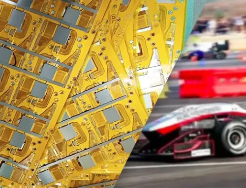
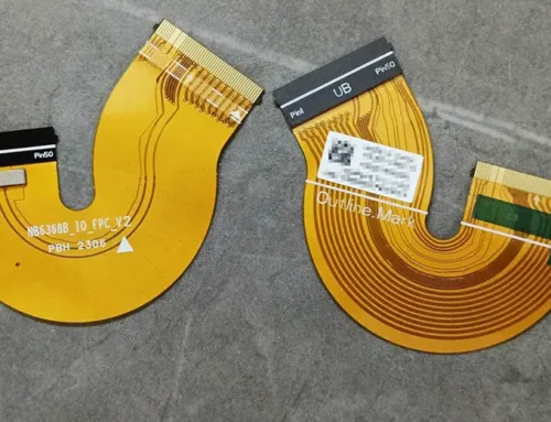
As shown in Figure 1, this study ingeniously combines UV printing with electroless plating technology for flexible circuit fabrication.

Fig.1 Schematic fabrication process of FPCs
UV-Assisted Electroless Plating Process
Specifically, a UV coating containing Ag/Fe₃O₄ catalyst is applied onto the surface of PET film or fabric. precisely curing the circuit structure through directional UV irradiation.
Subsequently, the chemical plating process deposits metal within the cured areas to form conductive layers.
The Ag/Fe₃O₄ catalyst is a nanocatalyst synthesized via electron beam irradiation reduction.
This additive manufacturing approach eliminates the need for traditional etching, reduces material waste, and simplifies the production process.
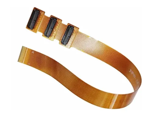
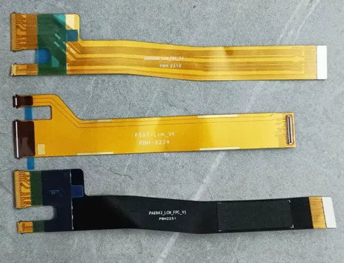
The fabricated flexible printed circuit (FPC) demonstrated reliable conductivity by driving LED illumination, validating its potential as a flexible circuit for wearable electronics, flexible displays, and sensors.
Durability of Fabric-Based Flexible Circuits
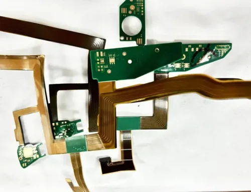
The digital photograph in Figure 2 displays the flexible circuit fabricated from a fabric substrate.

Fig.2 Fabric-based finger interconnect circuit fabricated on a textile substrate with a series connection
After approximately six months of storage in an indoor environment, the material still enabled LED illumination when driven by an external DC power source.
These results indicate the exceptional durability of fabric-based flexible circuits prepared via this method.
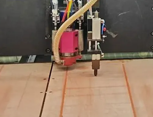
Figure 3 depicts the durability test of the FPC’s conductive layer, which involves periodic friction between rubber and the flexible conductive layer to evaluate its stability under dynamic stress and adhesion strength.
No signs of copper layer detachment or peeling were observed during testing, fully demonstrating the excellent bonding strength between the conductive layer and substrate (Figure 3(a)).
 An abrasion test equipment and FPC image")
Fig.3 (a) An abrasion test equipment and FPC image
Figures 3(b) and (c) show the real-time resistance change rate during cyclic friction testing.
Results indicate a resistance change rate below 20%, demonstrating good stability. Figures 3(d) to (g) display the microstructure of the FPC before and after friction testing. In the initial state (unfriction-tested), clear interfaces exist between copper particles with minimal gaps.
After friction testing, localized plastic deformation and displacement were observed on the copper particle surfaces. The interfaces between copper particles became tightly bonded and tended toward stability.
This occurs because copper particles embed into the coating structure of the flexible circuit, similar to tree roots penetrating soil, effectively enhancing adhesion and resisting some friction-induced wear (Figure 3(h)), thereby improving material durability.
Flexural Resistance and Repairability
Figures 3(i) to (k) show samples subjected to bending tests after friction testing to evaluate flexural resistance.
Results indicate the maximum resistance change rate remains below 9.0%.
Compared to earlier electron beam-cured flexible circuits, this method offers superior stability and enhanced precision.
Figure 3(l) illustrates the repair process for an incomplete conductive circuit.
During FPC board operation, localized circuit damage can be rapidly repaired by locating the faulty area through computer-aided measurement.
This capability holds significant value for achieving efficient and stable maintenance of flexible circuits in future applications such as robotics, robotic arms, and electronic devices.
Advantages of the UV + Electroless Copper Plating Method
This study innovatively combines UV light curing with electroless copper plating technology to develop a highly efficient flexible circuit manufacturing method based on Ag/Fe₃O₄ nanocatalysts.
The technique utilizes electron beam irradiation to synthesize a dual-functional catalyst, enabling precise circuit pattern formation and in-situ deposition of highly conductive copper layers simultaneously at low temperatures (≤45°C).
This approach avoids the complex processes of traditional etching and the high-temperature sintering constraints of printing methods.
Results demonstrate that thin-film-based flexible circuits exhibit a resistance change rate ≤14.6% after 10,000 flex cycles and 5,000 friction cycles, while fabric-based flexible circuits show a change rate ≤17.6% after 8,000 flex cycles and 2,000 friction cycles.
This work provides a novel approach for low-cost, high-efficiency flexible circuit manufacturing.