How Flexible PCBs Power Formula Student Race Cars: Design and Applications


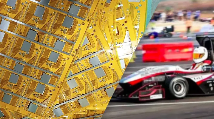
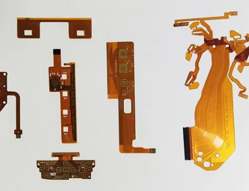
Flexible Printed Circuits (FPC) have emerged as an ideal alternative to traditional wiring harnesses in the electrical systems of Formula Student China race cars due to their lightweight, bendable nature, and high-density wiring capabilities.
Within the confined cabin space of FS vehicles, the electrical system faces dual technical challenges: ensuring operational reliability while optimizing spatial layout.
This is particularly demanding under extreme conditions such as high-speed cruising, instantaneous acceleration, sudden braking, and frequent starts and stops.
However, existing FPC design methodologies primarily target conventional automotive electronics applications, with insufficient research addressing the specific demands of FS.
Under extreme racing conditions—including high-frequency vibration, sustained high temperatures, and fluid corrosion—FPC reliability and durability face significant challenges, necessitating further research to optimize performance.
This paper proposes a universal FPC design methodology tailored to FS’s unique application scenarios.
Through a systematic design process, simulation-based optimization analysis, and production process refinement, it aims to enhance the space utilization and reliability of FS electrical systems while reducing wiring harness assembly and maintenance costs.
Finally, based on this methodology, flexible designs are implemented for traditional wiring harnesses across three typical FS application scenarios.
Flexible Printed Circuit Design and Fabrication
Leveraging the advantages of lightweight design, bendability, and high-density routing, FPCs demonstrate potential for applications across multiple FS electrical subsystems, including body, powertrain control, and battery systems.
This chapter proposes a universal FPC design methodology for multiple FS application scenarios, systematizes simulation-optimization analysis techniques for flexible circuits, and summarizes FPC manufacturing processes.
Design Methodology
The design methodology flow is illustrated in Figure 1 and comprises four steps: spatial geometric design, schematic design, board-frame design, and integration design.
1) Spatial Geometric Design
As shown in Figure 1a, the boundary dimensions, interface locations, and mounting methods of the FPC are determined based on the geometric constraints of the target electrical system’s environment, interface types, and their distribution characteristics.

Figure 1. FPC Design Flowchart
This stage also requires consideration of FPC mounting methods. Due to limited space and stringent lightweight requirements in racing vehicles, mounting methods such as hook-and-loop fasteners, double-sided tape, or soldering are commonly used, as illustrated in Figure 2.

Figure 2: FPC secured with a hook and loop fastener
2) Schematic Design
As shown in Figure 1b, determine component packages based on the target electrical system’s component types and wiring relationships.
Then, draft the actual circuit into a schematic diagram. This diagram covers only basic information such as electrical components and their interconnections, laying the foundation for subsequent design processes.
3) Panel Frame Design
As shown in Figure 1c, the final panel frame is determined by comprehensively considering boundary dimensions, the schematic diagram, interface locations, and their types.
During panel frame design, space is reserved for component placement. When implementing dual-layer or multi-layer routing, the panel frame width can be appropriately reduced.
4) Integrated Design
As shown in Figure 1d, based on the preceding steps, the schematic diagram, component packages, and board outline undergo integrated design to produce the final FPC.
Specifically, the designed board outline is imported into Electronic Design Automation (EDA) software.
Following the wiring relationships of components in the schematic, packages are placed at appropriate positions within the board outline. Electrical connections between components are then established through routing.
Following component placement, trace routing design commences.
Trace width and copper thickness selection are critical during routing, directly impacting the circuit’s current-carrying capacity and thermal dissipation performance.
In FPC design, different currents correspond to specific trace width and copper thickness parameters.
For FS low-voltage circuits, the rated current typically does not exceed 0.6 A.
Based on Table 1 data, a minimum trace width of no less than 0.2 mm at 35 μm copper thickness suffices to meet current carrying requirements.
The relationship between current and trace width is detailed in Table 1.
| 35 μm Copper Thickness | 50 μm Copper Thickness | 70 μm Copper Thickness | |||
|---|---|---|---|---|---|
| Current (A) | Trace Width (mm) | Current (A) | Trace Width (mm) | Current (A) | Trace Width (mm) |
| 4.5 | 2.5 | 5.1 | 2.5 | 6.0 | 2.5 |
| 4.0 | 2.0 | 4.3 | 2.5 | 5.1 | 2.0 |
| 3.2 | 1.5 | 3.5 | 1.5 | 4.2 | 1.5 |
| 2.7 | 1.2 | 3.0 | 1.2 | 3.6 | 1.2 |
| 2.3 | 1.0 | 2.6 | 1.0 | 3.2 | 1.0 |
| 2.0 | 0.8 | 2.4 | 0.8 | 2.8 | 0.8 |
| 1.6 | 0.6 | 1.9 | 0.6 | 2.3 | 0.6 |
| 1.4 | 0.5 | 1.7 | 0.5 | 2.0 | 0.5 |
| 1.1 | 0.4 | 1.4 | 0.4 | 1.7 | 0.4 |
| 0.8 | 0.3 | 1.1 | 0.3 | 1.3 | 0.3 |
| 0.6 | 0.2 | 0.7 | 0.2 | 0.9 | 0.2 |
| 0.2 | 0.2 | 0.5 | 0.2 | 0.7 | 0.2 |
Table 1 Relationship between FPC Copper Thickness, Trace Width, and Current
Post-routing processing phase
After completing the routing work, the post-routing processing phase begins.
First, perform routing optimization. As shown in Figure 3a, while adhering to principles such as minimizing trace paths and ensuring vertical access to components, it is also essential to design rounded corners or obtuse-angle transitions for trace bends.
This eliminates stress concentration and signal interference that could arise from right-angle or sharp-angle routing.
Next, teardrops are added, as shown in Figure 3b. Teardrops serve as transition zones between copper traces and pads, reducing stress concentration at connection points, enhancing strength, and improving reliability.
Subsequently, copper plating is applied. Copper plating enhances the FPC’s resistance to electromagnetic interference (EMI), which is particularly critical in applications like FS where electrical systems are densely packed, and EMI is significant, as illustrated in Figure 3c.
Finally, reinforcement is applied as shown in Figure 3d. Reinforcement plates are added to vulnerable areas such as connection points or stress concentration zones to enhance strength, ensuring the mechanical stability of the FPC under the extreme operating conditions of the FS.

Figure 3: FPC Bend Routing and Copper Patterning
Simulation Optimization Analysis
Under FS’s extreme conditions of high-frequency vibration and alternating temperatures, FPCs are prone to overload fractures and thermal expansion issues. Therefore, simulation optimization analysis is required after design completion.
Finite element models are established using computer-aided engineering (CAE) software (e.g., ANSYS).
Geometric models exported from EDA software are imported, and material parameters, boundary conditions, and load spectra are configured.
After mesh generation, simulations validate FPC strength and fatigue life, optimize structural design, and achieve lightweighting.
Utilize Computational Fluid Dynamics (CFD) software to construct thermal simulation models.
Simplify 3D models, define material properties, and calculate heat source power based on electronic component rated power consumption and heat dissipation paths.
Set boundary conditions such as ambient temperature and convective heat transfer based on FS operating conditions. Analyze steady-state temperature distribution and local overheating zones.
Enhance FPC thermal performance through optimized routing and micro-hole additions to ensure stable operation under high-temperature, high-dynamic conditions.
Manufacturing Process
The FPC production process primarily includes plate frame fabrication, coating application, circuit etching, film lamination, and curing/gold plating.
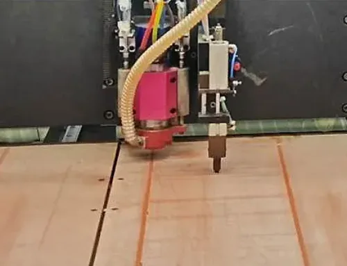
In substrate manufacturing, laser cutting is widely adopted for its high precision. However, it tends to generate burrs during complex shapes that are difficult to remove.
As shown in Figure 4, 3D printing technology employs layer-by-layer deposition to eliminate burr formation and enhance manufacturing accuracy for irregular substrates. For coating production, common techniques include electroplating, coating application, and lamination.

Figure 4: Example of a 3D printed board frame
Circuit etching achieves precise patterning of high-density fine lines through subtractive, fully additive, or semi-additive methods, ensuring circuit pattern accuracy.
The film lamination step incorporates electromagnetic shielding layers using conductive silver paste coating or metallized film composite technology to effectively suppress electromagnetic interference.
Addressing complex electromagnetic compatibility challenges arising from the coexistence of FS high-power motors and precision sensors, the electromagnetic shielding layer design achieves shielding effectiveness exceeding 55 dB in critical signal transmission zones, significantly enhancing the interference resistance of onboard low-voltage systems.
The final step involves solidification and gold plating using a chemical nickel immersion gold process. This enhances conductivity and oxidation resistance, ensuring long-term stable contact.
Flexible Circuit Board Applications
Building upon the aforementioned design methodology, this chapter implements flexible circuit board solutions for select FS electrical system wiring harnesses.
Key applications include transmission solenoid valve control circuits, battery signal acquisition circuits, and low-voltage control circuits.
Transmission Solenoid Valve Control Circuit
Recent FS models incorporating hybrid technology retain conventional automatic transmission structures within their powertrain configurations.
As shown in Figure 5, solenoid valves serve as critical control components in transmissions.

Figure 5: Transmission Solenoid Valve Control Circuit
Traditional designs employ wiring harnesses to connect them electrically to the Transmission Control Unit (TCU). This approach results in cluttered wiring with low space utilization.
Furthermore, the non-standardized nature of wiring harnesses hinders automation, making assembly processes highly labor-intensive.
This not only reduces production efficiency but also complicates subsequent maintenance.
FPC, with its advantages of thinness, flexibility, and high-density routing, effectively addresses these challenges.
› Schematic Design and Board Frame Configuration of the FPC System
Figure 5: The transmission solenoid valve control circuit follows the design methodology described earlier, integrating the control logic of the FS transmission valve plate solenoid valves to create the schematic diagram.
Fig 6 illustrates the electrical connections between each solenoid valve on the transmission valve plate and the TCU interface. Here, P0 represents the harness master interface, P1–P5 denote the five solenoid valve interfaces on the transmission valve plate, and P6 is the sensor interface.

Figure 6: Schematic Diagram of Transmission Solenoid Valve Control Circuit
The board frame shape was designed based on the geometric structure and spatial layout of the FS transmission solenoid valves.
As shown in Figure 7, five raised sections connect the solenoid valves, while the leftmost end of the board frame connects the sensor and the rightmost end connects the TCU interface.
› Routing Optimization and Environmental Adaptability Design
After completing the board frame design, schematic drawing, and package selection, routing and optimization operations were performed.

Figure 7: Transmission Solenoid Valve Control Circuit FPC Board Frame
First, considering the compact spatial layout within the transmission, a dual-layer wiring scheme was adopted to optimize space utilization.
For the high-temperature and oil-corrosion conditions of the transmission solenoid valve control circuit, a polyimide substrate was selected, whose oil resistance and thermal stability meet the design requirements.
To enhance mechanical strength and electromagnetic compatibility, a 45° grid copper plating scheme was implemented. This integrated copper-plating design balances structural rigidity with thermal-dissipation efficiency.
The final integrated design is shown in Figure 8, with the installation effect depicted in Figure 9.

Figure 8: FPC Design Diagram for Transmission Solenoid Valve Control Circuit

Figure 9: Actual Installation View of FPC for Transmission Solenoid Valve Control Circuit
Battery Signal Acquisition Circuit
In FS design, the power battery system must simultaneously meet dual technical requirements of lightweight construction and high reliability.
This imposes clear engineering constraints and performance demands on the wiring harness design for signal acquisition circuits.
Traditional wiring harnesses employ discrete routing structures, which not only introduce redundant system mass but also harbor failure risks due to fatigue fractures at solder joints under high-frequency vibration environments.
Against this backdrop, flexible circuit board technology emerges as an effective solution to overcome these technical bottlenecks.
› Battery Signal Acquisition Circuit Architecture
As illustrated in Figure 10, this section focuses on the flexible design of the signal acquisition circuit for the FS battery module, encompassing both temperature and voltage acquisition lines.
Thermistors tightly attached to the battery negative tab collect the temperature. Per the China Formula Student Competition Rules (2021), the battery management system must monitor temperatures of at least 30% of the cells, with monitoring points evenly distributed across different areas of the battery module (including the hottest and coldest regions).
Voltage measurement and control utilize a method that measures the potential difference between the battery’s positive and negative terminals.

Figure 10: Battery Signal Acquisition Circuit
› Schematic Design and Signal Measurement Strategy
Engineers first developed the schematic design based on the FS battery module’s signal acquisition requirements.
The voltage measurement circuit connects to the battery tabs via fuses (U1~U20), utilizing a series differential measurement circuit to capture individual cell voltage signals precisely.
The temperature measurement and control circuit incorporates 10 thermistors (R1~R10) in surface-mount packaging, closely adhering to the battery negative tab.
A voltage divider circuit converts resistance changes caused by temperature into real-time voltage signals. The detailed design is shown in Figure 11.

Figure 11: Schematic Diagram of Battery Signal Acquisition Circuit
› Board Frame Design and Structural Optimization
Based on the geometric model of the FS battery module, the shape of the flexible circuit board frame was determined by comprehensively considering voltage and temperature measurement methods, interface positions, and other factors. Figure 12 illustrates the battery module model.

Figure 12: Battery Module Model
The overall design of the battery signal acquisition circuit FPC board frame is shown in Figure 13.
The main trunk of the board frame is positioned between the two columns of electrode sheets in the battery module, with two main interfaces located at the trunk position.
Branches extend from the trunk to the gaps between every two electrode sheets, connecting to one side of the sheets while reserving space for thermistors and solder pads.

Figure 13: Battery Signal Acquisition Circuit FPC Board Frame
› Routing Optimization and Electromagnetic Compatibility Enhancement
After completing basic routing, engineers implemented multidimensional optimization for the battery signal acquisition circuit to suit its specific operating conditions, as shown in Figure 14.
Based on the distribution characteristics of battery tabs, gradient adjustments to line width and spacing effectively enhanced routing efficiency while minimizing interference.

Figure 14: Battery Signal Acquisition Circuit FPC Design Diagram
To mitigate electromagnetic interference from high-voltage wiring harnesses within the battery compartment, engineers added a grounded EMI shielding film, which significantly improved signal accuracy.
These optimization measures ensure signal acquisition precision while enhancing the FPC’s mechanical stability and electromagnetic compatibility under dynamic operating conditions. Figure 15 shows the final installation result.

Figure 15: Battery Signal Acquisition Circuit FPC Installation Diagram
Low-Voltage Control Circuit
As shown in Figure 16, within the FS, the front-end low-voltage control circuit serves as the signal transmission pathway for the vehicle’s electronic systems.
Through modular plug-in assemblies, it integrates functional modules such as the battery management system and insulation detection system.
Utilizing low-voltage signals, it facilitates command transmission and operational coordination among various units, providing core assurance for intelligent vehicle control and safety protection.
Traditional wiring harnesses, characterized by complex nodes and redundant routing, are prone to poor contact or signal attenuation under FS’s high-frequency vibration and shock conditions, compromising system stability and response speed.
Furthermore, these harnesses struggle to accommodate the compact layout and irregular surface mounting requirements of racing vehicles, resulting in inefficient assembly and difficult fault diagnosis.

Figure 16: FS Low Voltage Control Circuit
› Modular Schematic Design and Functional Isolation
Engineers developed the schematic design based on FS’s control signal acquisition requirements. The schematic adopts a modular plug-in structure.
Functional units such as the Battery System Power Distribution (BSPD) main contactor and Tell-Tale Alarm Lamp (TSAL) are implemented as independent modules rather than being directly integrated onto the FPC.
This physical isolation enables rapid fault localization and replacement while facilitating future system configuration expansions. Figure 17 illustrates the specific design.

Figure 17: Low Voltage Control Circuit Schematic
In the figure, Plug1–3 represent control signal input/output ports, while BSPD1–2, Terminal Block (TB) 1–2, TSAL1–2, and relays Relay1–4 serve as module connectors.
› Board Frame Determination and Interface Packaging
Engineers determined the shape of the FPC board frame based on the FS car front geometry model, comprehensively considering factors such as module mounting positions, FPC connection methods to the car body, and interface locations.
Components involved in this section primarily include module interfaces and wire interfaces.
Engineers selected appropriate packaging based on module design requirements and the spatial constraints of the race car body. Fig 18 shows the low-voltage control circuit FPC routing.

Figure 17: Low Voltage Control Circuit Schematic

Figure 18: Low-voltage control circuit FPC routing diagram
› Routing Optimization and Assembly Reliability Enhancement
To address the heterogeneous distribution of multiple interfaces and routing redundancy in the low-voltage control circuit, engineers implemented a collaborative optimization design for the FPC.
First, engineers reserved a flexible deformation allowance through redundant board frame area design to accommodate the body’s irregular curved surfaces, reducing routing complexity and enhancing structural conformity.
Second, engineers adopted a dual-layer routing architecture, significantly improving spatial integration efficiency.
This approach simultaneously reduces connector count, simplifies assembly processes, and effectively mitigates contact failure risks caused by mechanical vibration through optimized contact interface design.
It provides structural assurance for reliable low-voltage control circuit operation, with the final assembly shown in Figure 19.

Figure 19: Low-voltage control circuit FPC assembly diagram
The aforementioned design, manufacturing methods, and application examples provide reference for FPC design and implementation in FS systems.
Conclusions
Addressing the reliability demands of FS electrical systems under extreme operating conditions, this paper proposes a flexible solution tailored to racing characteristics, summarized as follows:
1) This study introduces a universal flexible circuit board design methodology tailored to the unique application scenarios of FS.
Through a systematic workflow encompassing spatial geometric design, schematic design, board-frame design, and integrated design—combined with simulation optimization analysis and manufacturing process refinement—it establishes a design paradigm to enhance spatial utilization and reliability of FS electrical systems.
2) Using this methodology, engineers successfully applied flexible circuit technology to critical FS electrical systems.
Engineers implemented flexible circuit solutions in transmission solenoid valve control circuits, battery signal acquisition circuits, and low-voltage control circuits, validating their engineering applicability under complex operating conditions.
This research offers insights for applying FPCs to circuit flexibility in Formula Student racing.
Future studies will focus on FPCs’ collaborative performance within complex systems and their potential for cross-domain applications, supporting continuous innovation and development in Formula Student racing and other high-performance electronic systems.