Design Considerations for FPC Flexure Zones


The design of the bend zone in FPCs is the most critical and challenging aspect of the entire product design. Improper design can lead to premature failures such as circuit breaks and cover film damage.
This article addresses key considerations for designing the bend zone of flexible circuits, which can be approached from electrical, mechanical, material, and manufacturing perspectives.
Flexible Printed Circuits (FPCs) are essential for modern electronics, enabling compact, lightweight, and reliable connections in everything from smartphones to medical devices.
However, the true reliability of FPCs is determined not by the overall circuit, but by their flexure zones—the high-energy-density regions where most mechanical stress is concentrated.
According to IPC-2223 standards and industry field data, over 90% of flex PCB failures originate in these bend areas, even when circuits pass standard specifications ([1], [2]).
Flexure Zones: The Highest Energy-Density Regions
Flexure zones are not mere routing leftovers; they are the heart of FPC reliability. These areas act as mechanical energy reservoirs, storing, releasing, and concentrating stress during bending and flexing cycles.
Treating them as afterthoughts in design can lead to premature, costly failures. Effective “FPC flexure zone design” and awareness of “flex PCB bending area failure” are therefore critical for engineering robust flexible circuits.
What a Flexure Zone Actually Is
A common misconception is equating a flexure zone with a simple bend line as shown in CAD drawings. In reality, a flexure zone is a physical volume—not a line—where mechanical strain is distributed across a length of the FPC.
Advanced strain mapping studies ([3]) reveal that stress propagates far beyond the visible bend, especially when enclosure geometry or assembly tolerances vary.
This hidden length is why failures often occur outside marked bend areas, confounding root-cause analysis.
Designers must account for the real-world spread of strain, considering how enclosure and assembly variables influence the flexure zone’s shape and size.
Understanding flexure zones as three-dimensional volumes, rather than lines, is key to preventing unexpected failures.

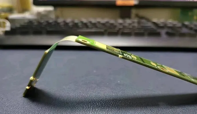
FPC Bend
Life Cycle of a Flexure Zone: From Assembly to Fatigue Failure
Installation Phase
During assembly, flex circuits often experience one-time over-bending as installers fit them into compact enclosures.
Human handling introduces uncontrolled load cases that frequently exceed design assumptions ([4]). These transient stresses can plant the seeds for early fatigue and micro-cracks, even before the product is powered on.
Operational Phase
Once installed, FPCs are subjected to micro-flexing caused by vibration, thermal expansion, cable drag, and connector actuation.
Even in “static” applications, housing movement and minor operational stresses contribute to cumulative fatigue in flexure zones.
Aging Phase
Over time, copper conductors work-harden, adhesives begin to creep, and coverlay materials fatigue.
These slow processes make failures appear late in product life, often seeming “random” and difficult to diagnose. Studies show that fatigue life can vary up to 10x depending on flexure zone design and materials ([5]).

Life Cycle of a Flexure Zone
Stress Is Not Symmetrical: Understanding Inner vs Outer Bend Damage
Mechanical stress in a flexure zone is not distributed evenly. The inner radius of a bend experiences compressive forces, leading to dielectric buckling and adhesive shear failure, while the outer radius is subjected to tension, causing copper elongation and micro-crack initiation.
The position of the neutral axis—the plane where no strain occurs—shifts with copper thickness, altering the risk profile for failures.
Stack symmetry in FPC design is therefore most critical in flexure zones, as it minimizes uneven stress and extends product life ([6]).
Designing Flexure Zones Backward: Start from Failure, Not from Rules
A highly effective—yet seldom adopted—approach in FPC design is to start from failure analysis rather than from design rules. Instead of asking, “What rules should I follow?”, professional designers ask:
- Where will copper crack first?
- Where will delamination initiate?
- Where will stiffness suddenly change?
By identifying these high-risk zones first, you can proactively:
- Move likely failure points away from critical circuits
- Spread mechanical strain across a length, never a single point
- Minimize abrupt changes in stiffness, which are notorious for triggering early failures ([1], [2])
This reverse-engineering mindset ensures reliability is built into the design—rather than retrofitted by compliance.
Geometry Choices That Quietly Decide Flexure Zone Survival
Seemingly minor geometry decisions can determine whether a flexure zone survives its intended life cycle. For instance, smooth, gradual curvature always outperforms any “minimum bend radius” calculated from datasheets ([3]).
- Trace length matching is often less important than matching strain across traces, especially in bend areas.
- Serpentine traces can either distribute strain or concentrate it, depending on implementation. Used wisely, they help; misused, they become failure sites.
- Copper density consistency within flexure zones reduces localized strain, often mattering more than impedance control for long-term survival.
Materials Behave Differently Inside Flexure Zones
Most manufacturers simply list materials; few explain how those materials behave under real flexing. Understanding these behaviors is essential for reliability.
Copper Type Under Repeated Flex
- Rolled Annealed (RA) copper offers superior fatigue resistance, with a microstructure that allows for repeated bending ([4]).
- Electrodeposited (ED) copper is more prone to micro-cracks and early failure when flexed.
- Counterintuitively, thicker copper isn’t stronger in flexure zones—greater thickness increases strain at the outer radius and accelerates failure.
Dielectrics and Adhesives
Adhesive-based vs. adhesiveless constructions have different risks: adhesives can creep or shear under long-term strain, while adhesiveless circuits offer better dimensional stability ([5]).
Long-term deformation, especially under sustained bending, is often governed by the adhesive’s mechanical properties rather than the base film.
Coverlay Performance Under Bending
Coverlay cracking is a common precursor to copper failure. The geometry of coverlay openings and the placement of their edges are critical—sharp or misaligned openings amplify stress, reducing flexure life.
| Aspect | Material / Design Option | Behavior in Flexure Zones | Impact on Reliability | Key Design Insight |
|---|---|---|---|---|
| Copper Type | Rolled Annealed (RA) Copper | Grain structure aligns with rolling direction, allowing repeated bending without crack initiation | Excellent fatigue resistance and long flex life | Preferred copper type for dynamic or high-cycle flex applications |
| Electrodeposited (ED) Copper | Random grain structure promotes micro-crack formation under cyclic strain | Higher risk of early failure in flex zones | Avoid ED copper in areas subjected to repeated bending | |
| Copper Thickness | Thicker Copper Foil | Increases strain at the outer bend radius during flexing | Accelerates crack formation and fatigue failure | Thinner copper often outperforms thicker copper in flex regions |
| Dielectric Construction | Adhesive-Based Flex | Adhesive layer can creep, shear, or deform under sustained bending | Long-term reliability limited by adhesive properties | Suitable for static or limited-flex designs only |
| Adhesiveless Flex | Eliminates adhesive layer, improving dimensional stability | Superior long-term mechanical performance | Recommended for dynamic flex and high-reliability designs | |
| Long-Term Deformation | Adhesive-Dominated Structures | Deformation governed more by adhesive mechanics than base film | Progressive mechanical degradation over time | Evaluate adhesive viscoelastic behavior, not just film strength |
| Coverlay Design | Poorly Designed Openings | Sharp or misaligned edges concentrate stress during bending | Early coverlay cracking leading to copper failure | Optimize opening geometry and edge placement |
| Optimized Coverlay Geometry | Smooth transitions reduce localized strain | Extends flex life and protects copper traces | Coverlay design is as critical as copper selection |
Features That Should Never Cross a True Flexure Zone
Preventing failure in flexure zones is not about following a checklist, but understanding why these features are high risk:
- Vias and Plated Through Holes (PTHs): Even reinforced, they act as stress risers and crack initiation sites.
- Pads, test points, fiducials: All introduce local stiffness discontinuities and focal points for fatigue.
- Sharp copper transitions: These create micro-stress zones prone to crack initiation.
- Stiffener edges too close to bends: Abrupt changes in support lead to delamination and early failure.
Designers must avoid placing these features within or near flexure zones, as even minor violations can dramatically reduce product lifetime ([6]).
Rigid–Flex Transitions: When Flexure Zones Meet Structural Boundaries
The interface between rigid and flex areas is a prime site for stress amplification:
- Transition zones can migrate the neutral axis, concentrating strain at the interface.
- Best practices include tapering copper and dielectric layers, using gradual geometry changes, and selecting prepregs that maintain flexibility and adhesion ([7]).
- Improper prepreg selection may stiffen the interface, increasing the risk of cracking in adjacent flexure zones.
Designing Flexure Zones for Manufacturability, Not Just Reliability
While reliability is paramount, manufacturability often dictates whether flexure zones perform as designed in real-world production. This aspect is underappreciated but delivers substantial value:
- Film lamination tolerances: Small variations in lamination pressure or alignment can shift the neutral axis, concentrating stress and reducing fatigue life ([1]).
- Coverlay registration drift: Misalignment during coverlay application is common in high-volume runs, leading to exposed traces, inconsistent strain distribution, and premature coverlay cracking.
- Etch compensation: The need to compensate for copper etch-back alters trace geometry, which can throw off strain balance and introduce weak points.
- Tight design margins: Margins that work for prototypes often fail during scale-up; real-world process variability requires robust tolerance stacking in all flexure zone features ([2]).
Reliability in the lab is not enough—true success means flexure zones survive the realities of mass manufacturing.
How to Validate a Flexure Zone Before Mass Production
Electrical testing alone cannot reveal mechanical weaknesses in flexure zones. The most robust validation strategies include:
- Static bend testing: Holding the flexure at its maximum designed bend for an extended period reveals early material or adhesion failures.
- Dynamic cycling: Repeated flexing (hundreds to thousands of cycles) exposes fatigue and crack initiation that static tests miss ([3]).
- Abuse testing: Simulating worst-case handling during assembly uncovers weaknesses related to human error and process variation.
- Prototyping: Building and testing early prototypes in real enclosures is the gold standard for exposing flexure zone vulnerabilities before mass production.
Practical Flexure Zone Design Checklist
A concise, actionable checklist ensures that flexure zones are designed for real-world survival:
- Can this zone survive misalignment?
- Can it survive human handling?
- Is the strain distributed or localized?
- Does stiffness change abruptly?
- Have manufacturing tolerances been included?
Teams that use this checklist catch hidden risks before they become costly field failures.
Final Insight: Flexure Zones Are Mechanical Components, Not Layout Areas
The ultimate mindset shift: treat every flexure zone as a mechanical spring—not just a layout area for routing traces. Mechanical reliability underpins electrical reliability. The best flex designs don’t merely “meet limits”—they avoid them by:
- Proactively managing mechanical stress
- Designing with both manufacturing and end-use in mind
- Validating performance through rigorous, real-world testing
Conclusion
Flexure zones are the silent arbiters of flexible PCB reliability. While design rules and materials lists provide a starting point, true reliability and manufacturability are achieved only when flexure zones are treated as critical mechanical components.
This approach merges engineering science with real-world production realities.
By understanding the complex interplay of geometry, materials, manufacturing tolerances, and actual use conditions, engineers can anticipate failure modes, design for both scale and performance, and validate their solutions before costly issues arise.
The best flex designs don’t simply pass tests; they prevent failure by distributing strain, minimizing abrupt stiffness changes, and accommodating the variability of mass production.
In short, the future of FPC reliability lies not just in compliance but in proactive, holistic flexure-zone engineering.
This mindset shift enables manufacturers and designers to deliver robust, reliable electronics that perform flawlessly through their intended lifecycle.
References (continued):
- IPC-2223: Sectional Design Standard for Flexible Printed Boards
- “Failure Mechanisms in Flex Circuits,” Journal of Electronic Packaging, 2022
- Flex Interconnect Technologies, “Bend Geometry and Fatigue Life,” Application Note, 2023
- DuPont, “Copper Metallurgy in Flexible Circuits,” Technical White Paper, 2021
- Panasonic, “Adhesiveless Flex Circuits: Reliability Advantages,” Materials Bulletin, 2022
- Rogers Corporation, “Avoiding Stress Risers in FPC Design,” 2021
- Taiyo America, “Rigid-Flex Transition Engineering,” Design Guide, 2023

