Flexible Printed Circuits on Textiles via Screen Printing for Wearable Electronics


The principle of flexible electronic printing technology involves using inks with electronic functionality to fabricate electronic devices or circuits on flexible substrates through precision printing techniques. The printed circuits possess corresponding electronic capabilities.
Flexible electronic printing technology holds broad application prospects in radio frequency identification (RFID) tags, sensors, thin-film transistors, supercapacitors, and other fields.
Printing is a relatively low-cost preparation method for depositing conductive materials onto substrates, primarily categorized into contact and non-contact printing.
Currently, the most widely used techniques are screen printing and inkjet printing. Substrates for flexible circuits primarily include paper-based substrates, polymer substrates such as polyimide (PI) and polycarbonate (PC), and textile-based substrates.
Compared to conventional polymer circuit boards, textile circuits are lightweight and skin-friendly, indicating significant application potential for textile-based printed circuits in wearable electronics. Each flexible substrate undergoes interactions between the substrate and ink during printing.
Common printing materials include conductive silver paste, gold, silver, copper, graphene, carbon nanotubes, etc.
This study employs silver-clad copper ink to fabricate fabric-based printed circuits via screen printing.
Experimental Section
Materials and Instruments
NS101-M monochrome single-station screen printer, DLX890C multimeter, ND602 curing oven, MD5060 vacuum exposure unit, plate drying cabinet, NA104 manual squeegee, digital flat-head thickness gauge, high-precision gold-gram electronic scale, squeegee, 80-mesh screen frame, 40 mL stainless steel cup, tracing paper, mixing rod, silver-coated copper powder, transparent printing paste, polyester-cotton plain weave fabric.
Experimental Procedure
Preparation of Printed Circuit Screen: Mix photosensitive emulsion according to specified ratio and degas for 12 hours.
In a darkroom environment, use a squeegee to repeatedly scrape the screen from bottom to top twice on both sides, then place it in a drying oven.
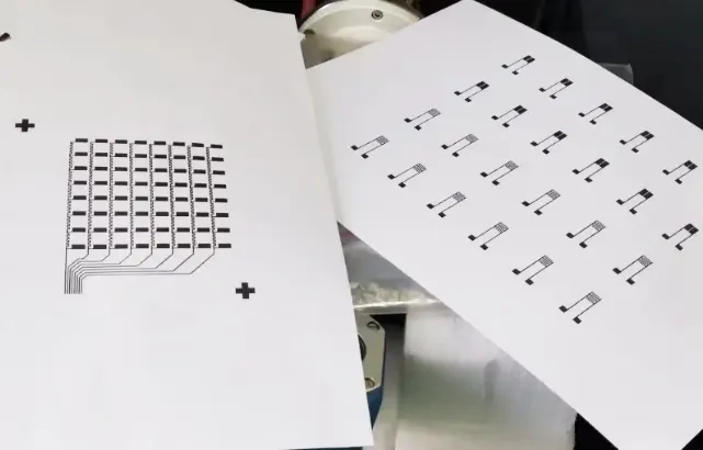
Print the design pattern onto tracing paper. Perform vacuum exposure on both the printed pattern and the screen.
Clean and dry the screen in a rinsing tank using a high-pressure water gun. The printed circuit pattern measures 25cm in length and 0.2–1.0cm in width.
Selection of conductive material and base fabric:
Choose silver-coated copper powder and prepare conductive ink using transparent adhesive paste at a 3:5 ratio.
Select polyester/cotton 4/6 plain weave fabric as the base material.
Ink Preparation and Circuit Formation:
Place the polyester/cotton plain weave fabric on the printing table. Using a squeegee at a 30° angle, apply one pass of silver-clad copper ink onto the fabric.
Prepare flexible circuits by applying 1, 3, and 5 layers, respectively.
Testing
» Thickness Testing
Using a digital display thickness gauge, measure the thickness of 1, 3, and 5 layers applied to the three different materials. Test each sample five times.
» Conductivity Testing
Connect the DLX890C multimeter, alligator clips, and copper plate electrodes to measure the effect of different print counts and line widths on the conductivity of printed circuits.
» Fabric Flexibility Test
Select 4 samples with identical line widths and printing frequencies for bending tests, observing resistance changes. Position the bending point at the center of the printed circuit.
After bending, the left and right sides of the printed circuit form angles of 0°, 30°, 60°, and 90°. Compare resistance after every 100 bends to investigate how angle and number of bends affect the conductivity of the samples.
Results and Discussion
Thickness Analysis
Silver-clad copper ink was applied to polyester-cotton plain weave fabric via squeegee coating. A single pass yielded a thickness of 0.050 mm ± 0.007 mm.
Three passes resulted in a thickness of 0.100 mm ± 0.005 mm. Five passes produced a thickness of 0.180 mm ± 0.004 mm.
As the number of scraping passes increased, the thickness of the conductive metal layer also increased.
With more printing passes, the circuit thickness increased, and the integrity and uniformity of the circuit gradually improved.
The printed thickness tended toward uniformity, with smaller fluctuations in error.
Figure 1 shows the thickness error bars for silver-clad copper ink at different printing layers. Overall thickness is relatively uniform: ±0.7% error for 1 layer, ±0.5% for 3 layers, and ±0.4% for 5 layers.
Figure 1: Effect of printing layers and line width on the thickness of silver-clad copper ink
Conductivity Analysis
This section investigates the impact of varying printing layers and line widths of conductive silver-clad copper ink on the conductivity of printed circuits on fabric.
After one application of silver-clad copper ink, resistance ranged from 79.62 to 480.28 Ω. Following three applications, resistance ranged from 6.56 to 35.24 Ω. After five applications, resistance ranged from 4.72 to 33.02 Ω.
Figure 2 shows the resistance variation and error for different printing frequencies and line widths of silver-clad copper ink.
The upper-right image depicts physical samples printed with varying frequencies. Figure 2 indicates minimal resistance fluctuation in the printed circuits.

Figure 2. Effect of printing times and line width of silver-coated copper ink on resistance.
Resistivity calculation follows Formula (1):
R = ρ l/A (1)
Where: R is resistance, ρ is resistivity, l is length, and A is cross-sectional area.
A single printing pass yields measurable resistance, confirming the formation of a conductive path.
While resistance is relatively high, its distribution is uneven. Resistance decreases as the number of printing passes increases.
When print width remains constant, increasing print cycles thickens the layer, enlarging the cross-sectional area for the same width.
According to resistivity formula (1), with fixed resistivity ρ and length l, the resulting resistance R decreases.
Therefore, resistance gradually diminishes with increasing print cycles. Resistance fluctuations also decrease as print cycles increase.
This occurs because, as printing frequency increases, the printed circuit approaches completeness, exhibiting relatively stable resistance trends with reduced error fluctuations.
The difference between single-printing and triple/quintuple-printing is notably pronounced. This stems from the simpler particle distribution network in single-printing, resulting in less efficient current flow.
Comparing three and five prints, the resistance difference is smaller; printing twice more does not result in a noticeable change in resistance.
Effect of Bending Degree on Conductive Stability
After balancing effectiveness and cost considerations, four samples featuring 1cm line width and 0.1mm printing thickness using silver-clad copper ink underwent bending tests to observe resistance changes.
This study investigates how different printing thicknesses and line widths of conductive ink affect the conductivity of printed circuits on polyester-cotton fabrics.
Figure 3 shows resistance data for silver-clad copper printed circuits with a line width of 1.0 cm and a printing thickness of 0.1 mm, bent at angles of 0°, 30°, 60°, and 90°.
As shown in Figure 3, when the printed width and thickness are consistent, the resistance gradually increases with the number of bends.
Initial bending tests show significant resistance changes. As bending cycles increase, a relatively stable layered structure forms at the bend location, causing resistance changes to gradually decrease and the curve to flatten.
As the post-bend angle decreases, resistance gradually increases.
A 0° post-bend angle has the most significant impact on the printed circuit, causing a noticeable decline in conductivity.
Bending angles of 30°, 60°, and 90° have a lesser effect on conductivity, with minimal resistance variation.

Figure 3: Effect of the bending angle of silver-coated copper ink on resistance.
Conclusion
This study employed conductive ink formulated with silver-coated copper powder as the conductive material.
Circuits were printed onto polyester-cotton plain weave fabric via screen printing to fabricate flexible printed circuits based on fabric substrates. The conclusions are as follows:
(1) With identical materials, lengths, and printed line widths, increasing the printed circuit thickness reduces resistance, minimizes error fluctuations, and enhances conductivity.
(2) For the same material, identical length, and consistent printed circuit thickness, resistance decreases as printed line width increases.
(3) For circuits printed with identical line width, material, and thickness, resistance gradually increases with repeated bending cycles. Stability improves at bending angles exceeding 30°.
In summary, controlling other variables constant, printed circuits exhibit optimal conductivity at a thickness of 0.18mm and a line width of 1cm. Resistance is minimally affected by bending angles of 30°, 60°, and 90°.
The optimal manufacturing process for flexible printed circuits, summarized in this paper,r holds practical value for industrial production and provides a reference for future smart garment development.