Flexible Electronics–Enabled RF Signal Processing Circuits for Miniaturized Missile Systems


With the widespread operational deployment of unmanned platforms, miniaturized, low-cost, and mass-produced munitions will become an inevitable trend in future weapons development. Therefore, designers must minimize the volume ratio of onboard electronic equipment, controlling it within 15% to 20% to reserve more space for warheads and propulsion systems.
Miniaturization Challenges in Next-Generation Munitions
However, traditional rigid circuit system structural design and assembly capabilities have reached their limits, struggling to meet functional and performance requirements within the compact, confined, and irregular spaces inside munitions.
Advantages and Architectural Impact of Flexible Electronics
Flexible electronics, as an emerging form of electronic technology, enable adaptive structural configurations that fully utilize irregular curved surfaces, thereby meeting the requirements for miniaturization and conformal integration.
At the same time, this technology introduces entirely new design philosophies and paradigms for the functional architecture distribution of electronic systems.
Classification and Characteristics of Flexible Electronics Technologies
Based on scale, researchers categorize flexible electronics technology into two technical directions: circuit flexibility (millimeter scale) and chip flexibility (micrometer scale).
Circuit flexibility utilizes polyimide or polyurethane films as substrates, integrating diverse functional components onto flexible printed circuit boards.
These circuits, characterized by lightweight, thin profiles and excellent bendability, allow designers to arrange them freely according to spatial layout requirements, enabling movement and expansion/contraction in three-dimensional space.
When mounted onto matching specialized carrier boards, they meet the demands for high density, miniaturization, and high reliability.
Flexible circuits offer advantages including light weight, thin profile, compact size, high integration, excellent flexibility, high-temperature resistance, vibration tolerance, ease of non-standard installation, and superior insulation.
They meet the demands of complex electronic equipment for multi-layer high-density routing and three-dimensional assembly.
Flexible Circuit Integration and Chip-Level Flexibility
Multi-Chip Modules (MCM) incorporate MCM sockets and surface-mount components on flexible circuit boards.
Flexible interconnect cables enable board-to-board, board-to-compound housing, and device-to-device connections, facilitating power distribution and data transmission between MCMs.
Additionally, engineers add fixed interface connectors to the circuit board, enabling flexible assembly between MCM boards and interconnects, thereby enhancing circuit repairability and flexibility.
Chip flexibility builds upon circuit flexibility by significantly reducing the bending stiffness of integrated circuits through thinner substrates, enabling free bending at the chip level to meet more demanding system flexibility requirements.
In recent years, flexible integrated circuit chips manufactured using SOI (Silicon-on-Insulator) and silicon wafer thinning processes have proliferated, demonstrating the capability to implement complex functions while related technologies continue to mature.
American Semiconductor unveiled the world’s first flexible microcontroller in 2013, featuring a thickness of approximately 60 µm and fabricated using silicon-on-polymer technology.
Military Application Status and Research Motivation
As equipment systems increasingly demand lighter weight and smaller size, the military application needs for flexible electronics technology have become increasingly prominent.
Currently, engineers primarily integrate flexible circuits into flexible antennas and flexible interconnects, while complete systems lack component-level applications.
This stems from flexible circuits being an emerging technology, lacking accumulated technical experience and reliability test results in military applications.
To accelerate the adoption of flexible circuit technology in missile systems, it is imperative to develop flexible circuit solutions tailored to various functional components, including RF, optoelectronics, signal processing, and power supply modules.
Engineers must rapidly validate these solutions in terms of functionality, performance, and reliability, while progressively establishing corresponding design rules and testing standards.
At the same time, engineers should enhance flexible circuit design capabilities, reduce flexible board manufacturing costs, and promote the broader application of flexible circuit technology in missile systems.
In summary, existing rigid circuits struggle to meet the miniaturization and high-performance demands of missile-based circuit systems due to limitations in form factor and assembly methods.
Driven by the miniaturization requirements for communication data link systems under ultra-small missile diameter constraints at a certain aerospace institute, this paper adopts non-planar conformal molding as the solution path.
Leveraging its foundation in flexible design and integration, it conducts research on flexible RF signal processing circuit technology based on FPC and develops a flexible signal processing prototype for functional and reliability verification.
Key Technologies for Flexible Signal Processing Circuits
Driven by trends toward intelligence, networking, and integration, signal processing circuits have become core components of modern electronic information systems.
However, as demands for signal processing performance, reliability, resilience, and uniqueness grow in complex environments, traditional “rigid” circuit designs can no longer meet diverse modern applications. Consequently, circuit flexibility will become a major trend in miniaturization.
Among these, flexible circuit optimization design technology, flexible circuit manufacturing process technology, anti-interference technology for digital-analog mixed-signal systems, microsystem layout optimization and high-density integration technology, flexible cable-free connection technology, and flexible circuit optimization technology are key technologies for the flexibility of signal processing circuits.
Flexible Circuit Optimization Design Technology
Compared to traditional rigid circuit design, flexible circuit systems must account for the degree of bendability during design. This necessitates careful layout planning to ensure all components function properly after bending.
Layer count and thickness primarily constrain the bendability of flexible boards. To achieve a bending radius below 30 mm, designers typically keep the circuit layer count under 6 layers and control the circuit thickness below 0.4 mm.
If designers exceed 6 layers, they can employ a circuit stack-up design. Additionally, engineers enhance mechanical strength and stability during structural optimization of flexible circuits by strategically arranging the laminate structure.
When designing conductors on flexible circuit boards, engineers must consider circuit layout to minimize stress concentration during bending and twisting, preventing fractures or damage.
The minimum line width for flexible board sections is 10 mil, with a minimum line spacing of 10 mil. Engineers also employ arc-shaped routing to reduce stress concentration and prevent fractures.
Furthermore, rational circuit layout helps reduce the overall dimensions of the flexible circuit while ensuring performance integrity during bending.
For instance, when orienting components on the flexible board, designers should arrange all components perpendicular to the short edge of the bending direction and place them on the inner side of the bend surface to minimize stress during bending.
Simultaneously, increasing the spacing between components prevents mutual contact during bending.
Flexible Cable-Free Connection Technology
The fundamental principle of cable-free connection is integrating both electrical connections and thermal management into the spacecraft’s structural support system.
In traditional designs, the cable network (including cables, power distributors, and electrical connectors) accounts for approximately 10%–15% of the total mass, with 30% of that mass attributed to electrical connectors and solder joints.
Wireless connection technology significantly reduces the mass of electrical connectors and solder joints, enabling component weight reduction.
Flexible circuitry enables wireless electrical connections in electronic systems at three levels: Level 1 connects IC chips within a Multi-Chip Module (MCM); Level 2 links different MCMs.
Level 3: Connections between different MFS boards. Modules interconnect through flexible circuits to fully leverage the three-dimensional structure for adaptive deformation.
Their excellent insulation properties break free from the constraints of rigid board design, resolve thermal-mechanical fatigue issues at solder joints, and significantly reduce system weight and connection complexity.
Flexible Circuit Manufacturing Process Technology
Compared to traditional rigid circuit boards, the flexibility of flexible circuits stems from differences in substrate materials. The choice of flexible substrate material determines bendability, electrical properties, and mechanical characteristics.
Flexible board materials primarily consist of substrate materials and conductor materials. Substrate materials fall into three categories: polyimide (PI, with or without adhesive), polyester (PET, with adhesive), and polytetrafluoroethylene (PTFE), each further divided into adhesive-backed and non-adhesive sheets.
To achieve superior bendability, designers often choose adhesive-free PI substrates to reduce circuit thickness. Common copper foil conductor materials include rolled annealed (RA) copper foil and electrolytic (ED) copper foil.
Rolled annealed copper foil offers excellent flexibility, withstanding over a thousand dynamic flex cycles, making it suitable for products demanding high bendability. Additionally, due to copper’s high Young’s modulus, bending stiffness can be reduced by decreasing thickness while increasing width.
∗ Multiple advantages
Flexible circuits offer multiple advantages:
① Design and Production Efficiency:
Compact circuit design reduces the number of boards required and overall installation time.
② Material and Transportation Costs:
Lighter and smaller materials used in flexible circuits provide cost advantages in both materials and shipping.
③ Durability:
Flex circuits exhibit superior shock resistance and reduced susceptibility to environmental factors, thereby lowering replacement costs.
④ Integration:
The design flexibility and high integration of flex circuits minimize the need for connectors and cables, reducing hardware expenses.
⑤ Scalability:
Flexible circuits allow adjustment and upgrading as needed, saving substantial replacement and redesign costs during maintenance and upgrades.
∗ Flexible chip SIP packaging integration technology
To achieve fully flexible circuits, core chips undergo thinning during manufacturing to integrate with flexible substrates, forming flexible integrated circuits.
During this process, warping occurs in the thinned chips.
Therefore, research must address warping mechanisms and suppression techniques, along with completing studies on flexible chip SIP packaging integration technology.
(1) High-Reliability Manufacturing Technology for Ultra-Thin Chips
For the back-grinding thinning method, investigate the damage mechanisms caused by thinning processes on chips. Analyze the influence mechanisms and patterns of key process parameters—such as grinding wheel grit size, rotational speed, and feed rate—on chip defects.
Investigate the effects of coarse grinding, fine grinding, polishing, and etching on chip backside thinning, as well as their impact on surface roughness and warpage. Optimize the thinning process flow. Figure 1 illustrates the batch thinning process for single chips.

Figure 1: Single chip batch thinning process
(2) Warpage Suppression Technology for Ultra-Thin Chips
Warpage in ultra-thin chips primarily results from residual stresses within the damage layer formed during mechanical thinning. Chemical Mechanical Polishing (CMP) will be employed to minimize or eliminate this damage layer, thereby suppressing warpage.
(3) Flexible Chip SiP Packaging Integration Technology
Based on flexible chip bending stress analysis and reliability evaluation/optimization of interconnect processes, establish flexible chip SiP packaging methodologies to complete the packaging and processing of flexible chip infrared signal acquisition modules.
This involves designing and optimizing gold wire bonding structures resistant to bending fatigue; establishing standardized flexible chip SiP packaging processes; employing wafer thinning to reduce damage from backside thinning of flexible chips; and utilizing high-reliability flexible encapsulation materials.
Layout Optimization and High-Density Integration Technology for Information Processing Microsystems
In flexible RF information processing circuit design, certain components (RF, high-speed digital) cannot be directly integrated onto flexible boards due to performance and stability requirements.
The current approach employs rigid-flex board design, integrating RF signal transmission/reception and information processing microsystems onto a small-area rigid board, while distributing passive components, power supplies, interfaces, and other functional elements onto a large-area flexible board.
Research on layout optimization and high-density integration for communication processing microsystems primarily focuses on package specifications, chip selection, core functions, layout design, and high-density component integration. Specific approaches include:
(1) Package Specifications
To meet demands for miniaturization and high-density integration, 0402 or 0201 package sizes are selected, saving space while increasing layout density.
(2) Chip Selection
In the signal processing subsystem, the FPGA and FLASH core chips are implemented as bare die configurations. This reduces the size by nearly seven times compared to packaged chips and enables flexible circuit board design.
(3) Core Functions
Within the digital processing module circuitry, an FPGA+Flash core architecture is adopted to efficiently integrate signal processing, antenna selection, transmit/receive control, and external communication functions.
(4) Layout Design
A multi-layer ground and power reference plane stacking structure ensures strong electromagnetic absorption capability and excellent EMI characteristics, while also facilitating impedance design across signal layers.
(5) High-Density Component Integration
Flexible boards and layered stacking enable high-density component integration within minimal space, offering superior flexibility, integration, and reliability compared to traditional rigid boards and connectors.
Interference Suppression Techniques for Digital-Analog Mixed-Signal Systems
Flexible RF signal circuits achieve integrated implementation through rigid-flex boards. To address interference and noise issues such as digital crosstalk, power supply noise, and substrate noise, coordinated anti-interference design is implemented through circuit routing, layout design, and package design.
∗ Routing Design
Signal ground and RF ground are completely isolated by reducing ground loop area, lowering ground loop resistance and inductance, and implementing separate power supplies. This minimizes ground loop crosstalk on signals. The ground isolation configuration is shown in Figure 2.

Figure 2. Schematic diagram of territorial isolation
Impedance matching is performed for microstrip lines and striplines to ensure impedance matching between signal lines and transmission lines, thereby reducing signal reflection and crosstalk. Routing details are shown in Figure 3.

Figure 3. Schematic diagram of microstrip line wiring
∗ Layout Design
During layout design, avoid crossing high-speed digital signals with RF analog signals to minimize electromagnetic coupling between them. Utilize PCB stackup techniques to reduce electromagnetic radiation effects. The PCB stackup schematic is shown in Figure 4.

Figure 4: Schematic diagram of circuit board stack up
∗ Enclosure Design
Select enclosure materials with excellent insulation and shielding properties to minimize the impact of external interference on internal signals. Add shielding layers to the system exterior to reduce RF radiation and enhance RF shielding effectiveness.
∗ Power Supply Noise Suppression
Separate power supplies are used for different modules to prevent noise from digital modules propagating to analog modules.
Additionally, numerous filter capacitors are added at power supply entry points to reduce high-frequency noise and interference from external power supply fluctuations.
Flexible RF Signal Processing Circuit Design for Missile Applications
Overall Solution
To accommodate the irregular curved surfaces on the missile, the RF signal processing circuit employs a rigid-flex integrated design.
This maximizes utilization of the confined, irregular space by integrating digital processing and signal transceiver modules onto a small-area rigid board, while distributing power management and interface communication modules across a large-area flexible board.
The overall architecture is illustrated in Figure 5.
The red rigid board area houses the digital processing module, including FPGA, flash memory, crystal oscillator, and other chips.
The blue rigid board area contains the RF signal transceiver module, featuring RF transceiver processing, crystal oscillator, and related chips.
The yellow flexible board area manages power and interfaces, incorporating power supply and interface chips.
Additionally, the flexible board facilitates signal interconnection between the two rigid boards.

Figure 5: Overall Architecture Design
RF Transceiver Module
The RF transceiver module centers on the integrated RF function chip AD9361, primarily implementing RF signal transceiving and analog-to-digital conversion. The chip operates within a bandwidth of 47 MHz to 6.0 GHz, covering the target working range of 750 MHz to 3.0 GHz.
Digital Processing Module
The digital processing module circuit centers on an FPGA, model XC7A200T, primarily implementing signal processing, antenna selection, RF equipment power switch control, transceiver control, and external serial communication functions.
Power Management Module
The power management module circuit uses a DC/DC chip to convert the power supply voltage in real time to the device operating voltage and supplies power to the external RF transceiver components, internal RF transceiver components, FPGA, and interface chips.
Since the power supply is distributed across the flexible board area, a layout of one chip per power supply line is adopted to achieve PCB flexibility.
This chip also supports output feedback and enables functions to adapt to the FPGA power-up sequence.
Layout Design
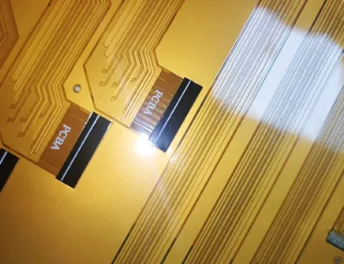
Based on the schematic, structural layout, and flexible PCB design principles, the layout design was completed, as shown in Figure 6: Physical Diagram of Flexible RF Signal Processing Circuit.
The rigid board consists of 6 layers. The flexible board comprises:
– Rigid board: 6 layers with stackup sequence: Signal 01, Ground 02, RF Signal 03, Signal 04, Power 05, Signal 06; The flexible board is 4 layers with the following stackup: Signal 01, Ground 02, Power 03, Signal 04.

Figure 6: Physical diagram of the flexible radio frequency signal processing circuit.
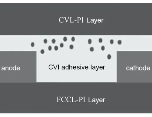
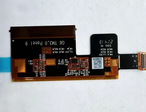
Rigid-Flex Board Fabrication
Fabrication involves three aspects: rigid-flex board production, component placement, and encapsulation, resulting in the flexible RF signal processing circuit shown in Figure 7.
The rigid board specifications are: 6 layers, thickness: 1 mm, substrate: FR4; the flexible board specifications are: 4 layers, thickness: ≤0.3 mm, substrate: PI, copper type: rolled copper. Laminated connections are employed at flexible board junctions.

Figure 7: Physical diagram of the flexible radio frequency signal processing circuit.
Structural and Assembly Design
Design requirements with strict spatial and weight constraints impose heightened demands on the structural and assembly methods of the flexible RF signal processing circuit.
The design adopts a rigid-flex board to ensure reliable circuit performance while achieving perfect conformity between the circuit board and the assembly structure.
During missile-mounted component assembly, the process employs adhesive bonding combined with screw fixation.
This method directly affixes the circuit board to the missile structure surface, enhancing vibration resistance while simplifying the assembly process and reducing spatial footprint.
Figure 8 illustrates the assembly of the flexible RF signal processing circuit.

Figure 8: Schematic diagram of flexible radio frequency signal processing circuit assembly
Prototype Validation
To validate the flexible RF signal processing circuit prototype, performance and environmental adaptability tests followed the requirements of an ultra-compact data link system from a certain aerospace institute.
Prototype Performance Testing
The flexible components completed power-up testing. Results indicated normal voltage values at all power supply output test points.
The FPGA and RF transceiver components powered up and operated normally. Figure 9 shows the transmitted signal spectrum test results.
The signal center frequency was 1.5 GHz, signal power was >-10 dBm, and signal reception sensitivity was -90 dBm, meeting the data link system specification requirements.

Figure 9: Spectrum Test
Temperature Cycling Test
The device underwent testing according to GJB1032A-2020, with an operating temperature range of −40 °C to 60 °C. Both low- and high-temperature holding periods were set at 30 minutes. All modules functioned normally during and after testing. Figure 10 shows the temperature cycling test.

Figure 10: Temperature cycling test
Random Vibration Test
The equipment underwent testing according to GJB1032A-2020 Environmental Stress Screening Methods for Electronic Products. Random vibration spectrum parameters were set as follows:
- 120–80 Hz: +3 dB/oct;
- 80–350 Hz: PSD=0.04 g/Hz;
- 3 350~2 000 Hz: -3 dB/oct;
Vibration axes: OX, OY, OZ; Test duration: 5 min (per axis)
All modules functioned normally during and after testing. Figure 11 shows the vibration test setup.

Figure 11: Random vibration test
Conclusion
Based on flexible FPC circuit technology, this work achieved breakthroughs in core technologies, including flexible circuit optimization design, flexible circuit manufacturing processes, anti-interference capabilities for mixed-signal digital/analog systems, microsystem layout optimization, and high-density integration.
A novel flexible RF signal processing prototype integrated and fabricated to achieve true structural–functional integration of the circuitry.
This significantly enhances space utilization efficiency within the irregular geometry of missile-borne platforms, meeting the structural constraints of ultra-small missile diameters (diameter 35 mm, length 40 mm).
It passed performance testing and temperature cycling/vibration tests according to the overall requirements of the data link system, meeting future development demands for lightweight, miniaturized, and highly reliable aerospace equipment.
This lays the technical foundation for the application and promotion of flexible functional components in missile-borne and satellite-borne platforms.