Flexible coating materials play an increasingly critical role in the modern circuit board industry as electronic products continue to evolve toward higher density, lighter weight, and greater mechanical reliability.
From flexible printed circuits (FPCs) to rigid-flex and high-reliability PCBs, these materials are widely applied to protect conductive traces, enhance environmental resistance, and maintain electrical performance under repeated bending, vibration, and thermal cycling.
Unlike traditional rigid coatings, flexible coatings are engineered to combine mechanical compliance with strong adhesion, chemical stability, and dielectric integrity, enabling circuit boards to operate reliably in demanding applications such as automotive electronics, consumer devices, medical equipment, and industrial control systems.
This article examines the key applications, performance requirements, and technological significance of flexible coating materials within the circuit board manufacturing ecosystem.
What are flexible coating materials?
Flexible materials are substances characterized by excellent flexibility, bendability, and foldability. Common examples include paper, polyvinyl alcohol (PVA), polyester (PET), polyimide (PI), polyethylene (PE), polyvinyl chloride (PVC), polypropylene (PP), OPP, and textile materials.
Depositing a functional thin film onto these flexible substrates not only preserves the base material’s softness and bendability but also modifies its surface properties, imparting new functionalities such as antistatic properties, electromagnetic wave shielding, thermal insulation, conductivity, and anti-reflective coatings—all representing advanced high-performance films.
Metals, ceramics, organic materials, and inorganic materials can all be used to deposit functional films on flexible substrates.
The primary methods for preparing various functional films on flexible substrates are: coating, chemical plating, and vacuum deposition.
1) Coating: Functional microparticles such as metals or oxides are mixed with an organic carrier to form a paste, which is then applied to the flexible substrate.
2) Electroplating: Utilizes electric current to reduce metal ions in solution, forming a metallic film on the substrate surface. This method applies only to conductive substrates.
3) Physical Vapor Deposition (PVD): Under vacuum conditions, specific materials are vaporized into atoms or molecules, or ionized into ions, and ultimately deposited onto the substrate.
Applications of Flexible Coating Materials in the New Industrial Revolution
Flexible coating materials boast extensive applications and diverse varieties, with new innovations emerging continuously. Over the past two decades of the 21st century, they have experienced vigorous development, advancing toward high technology, multifunctionality, and innovation across multiple industries and product types.
1) Packaging Industry: Non-transparent aluminum or transparent aluminum oxide coatings on flexible substrates are used for food packaging; magnetic alloy deposition or coating on flexible substrates serves for labels, coding, and identification.
2) Electrical and Electronics Industry: Capacitor films, power battery films, flip-chip packaging films.
3) Automotive Industry: Sunshade films, anti-fog films.
4) Construction Industry: Low-E films for windows.
5) Defense Industry: Radar reflector films, radar absorber films.
The application in the circuit board industry discussed herein represents a high-tech electrical material derived from innovations in the electronics and semiconductor integrated circuit sectors.
High-Performance Flexible Circuit Board Materials
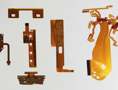
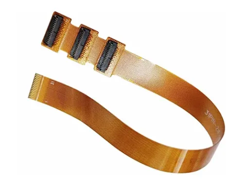
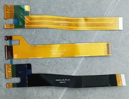
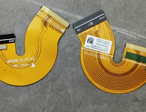
Flexible circuit boards, also known as flexible printed circuit boards (FPCBs), are commonly referred to as “flex boards” within the industry.
Flex boards are formed by laminating flexible copper foil substrates with soft insulating plastic films using adhesive bonding. Through processes such as printing and etching, the required circuit patterns are formed, enabling electronic signal transmission along these pathways.
Advantages of flexible circuit boards include: bendability, rollability, foldability, lightweight design, compact size, high component density, adaptable spatial layout, and high reliability.
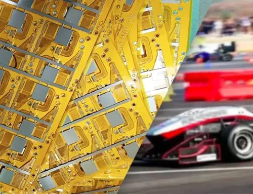
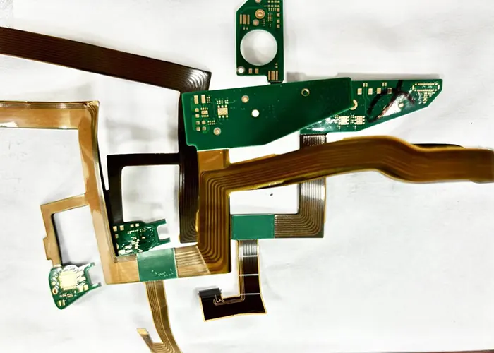
Flexible circuit boards find extensive applications in electronic computers and systems, various communication products, consumer electronics, high-speed rail, smart vehicles, and high-precision military equipment.
Flexible circuit boards primarily come in two types: three-layer flexible copper-clad laminates (3L-FCCL) using adhesive (epoxy resin), and adhesive-free novel flexible copper-clad laminates (2L-FCCL).
Three-layer flexible copper-clad laminates, due to the presence of adhesive, fail to meet the thermal resistance and flex endurance requirements of many modern electronic products, leading to a gradual decline in their application volume.
Two-layer flexible copper-clad laminates, offering superior thermal resistance and dimensional stability, have experienced rapid market growth with increasing demand.
As high-performance flexible circuits trend toward finer lines and thinner layers, both lamination and coating methods for 2L-FCCL struggle to adapt. This has driven innovation toward vacuum sputtering processes.
Research and Development of High-Performance Flexible Circuit Materials
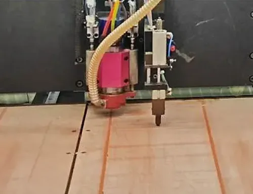
Currently, the world’s most advanced coating technology is the vacuum magnetron sputtering roll-to-roll coating machine. The following introduces relevant technical aspects regarding equipment characteristics, process conditions, and product performance for reference and discussion.
Equipment Characteristics
This equipment primarily deposits a nanoscale metal seed layer onto flexible substrates via vacuum magnetron sputtering, providing a uniform base layer for subsequent electroplating thickening.
The continuous production system supports flexible substrate speeds ranging from 2 to 12 m/min, with a maximum substrate width of 1600 mm. Its high production efficiency stands as one of the key advantages of this roll-to-roll vacuum coating equipment.
Additionally, the comprehensive system configuration ensures reliable implementation of the vacuum coating process:
- (1) Flexible substrate unwinding, rewinding, and web transport system.
- (2) Substrate surface baking and plasma pretreatment system.
- (3) Magnetron sputtering coating process execution system.
- (4) Oil-free, clean vacuum assurance system.
- (5) Working gas and reaction gas supply system.
- (6) Online film thickness parameter detection system.
- (7) Computer operation, control, and management system.
- (8) Water, electricity, and compressed air utility supply system.
Coating Process Flow Chart

Fig.1 Process flow diagram of the SNM flexible material thin film coating
The substrate PI is unwound and loaded into the equipment, adhering to the traction belt. After adhesion, the entire system undergoes vacuum pumping. Once the equipment pressure reaches the specified value, the coating process commences.
The PI film first enters the heating unit via the transfer system. Heating devices within this unit treat the substrate surface to desorb adsorbed gases.
Following heating, the material passes through an ion source pretreatment unit. Here, the process further desorbs adsorbed gases and activates the substrate surface, preparing it for the subsequent coating.
After pretreatment, the web enters the main vacuum coating chamber. It first passes through a specialized magnetron sputtering unit. The twin rotating targets within this magnetron unit deposit a metal or metal oxide adhesion layer onto the web surface (Fig. 2).

Fig.2 Schematic of the MF magnetron sputtering
Next, DC magnetron sputtering deposits a copper seed layer of specified thickness onto this adhesion layer (Fig. 3).

Fig.3 Schematic of the DC magnetron sputtering
Both magnetron sputtering techniques represent the most advanced and mature PVD technologies available today. They offer excellent film uniformity, high deposition rates, and easy control over film composition, facilitating industrial production and enabling seamless integration into continuous, automated operations.
After completing the coating, the system moves the substrate forward through an online film thickness inspection before winding the finished coating in the take-up zone.
Factors Affecting Film Properties and Quality
The vacuum coating process decisively influences film properties and quality, encompassing environmental conditions, technical parameters, and other related factors. The following sections detail the key aspects.
» Substrate Condition
As the coating carrier, the substrate must be of high quality. Coil edges should be straight, free of curling or flanges. Strip surface tension must be uniform, with high cleanliness—free of oil, dust, water, or pitting. Additionally, the substrate surface must be wrinkle-free and devoid of flaking marks.
» Sputtering Targets
As the core determinant of film quality, the target surface must be clean, with uniform target dimensions and composition. Purity must exceed 4N.
» Substrate Feed Rate During Processing
Under constant sputtering rate conditions, the substrate feed rate determines the film thickness.
Excessively high feed rates result in overly thin films, hindering subsequent process steps.
If the transport speed is too slow, excessive heat radiation to the substrate may cause wrinkling within the coating chamber, thereby compromising film quality.
» Background Pressure and Working Pressure
The process maintains the background pressure at the minimum level required to meet coating specifications. It primarily establishes a clean vacuum environment with minimal residual harmful gas molecules for process execution.
The process sets the working pressure to meet coating conditions and achieve optimal product quality.
Base pressure is a prerequisite for process execution, while working pressure ensures process execution. The two complement each other.
» Working Gas and Reaction Gas
Both the ion source startup and the magnetron sputtering target initiation of glow plasma require clean, dry argon (Ar). The process introduces this inert gas, which is therefore called the working gas and requires a purity of 5N.
The film system design requirements determine the type and flow rate of the reaction gas. The introduced gas dictates the resulting compound.
For instance, introducing N₂ deposits a nitride film on the substrate surface, while introducing oxygen generates an oxide film. Simultaneously introducing O₂ and N₂ allows deposition of a nitride oxide film on the substrate surface.
Reaction gas purity must exceed 5N. The flow rate and operating pressure of the reaction gas determine the properties of the deposited film layer. Different coating processes require varying flow rates and pressures for the reaction gas.
» Magnetron Sputtering Power Supply Performance
The magnetron sputtering power supply is an essential component for vacuum coating. Instability in electrical parameters directly impacts sputtering performance; abnormal sputtering operation compromises the quality of the deposited film.
A high-performance magnetron sputtering power supply configuration ensures stable and reliable coating processes. The film system design and target material determine the type of power supply configuration, such as DC, MF, or RF.
» Beyond the aforementioned conditions, engineers must also consider factors related to process execution.
These include circulating cooling water temperature, flow rate, and pressure; continuous and stable compressed air supply; cleaning and calibration of vacuum gauges; cleanliness of rollers in the drive system; and vacuum chamber cleanliness.
The film deposition process is an integrated system where every step can influence film quality. Therefore, engineers must give due attention to each step to achieve the desired results.
Product Performance
Products produced by magnetron sputtering exhibit dense, uniform coatings with low surface roughness, providing robust support for integrated circuit etching processes.
Rotary magnetron sputtering causes minimal damage to base films, offering excellent dimensional stability with low thermal shrinkage and expansion.
Product peel strength reaches 0.8 N/mm, exceeding the industry standard of 0.7 N/mm;
Excellent thermal and chemical resistance; high selectivity in copper layer thickness (Fig. 4).

Fig.4 The structure of SNM 2L FCCL product
Conclusion
(1) Flexible substrates are widely used because of their inherent flexibility and bendability.
Substrate selection varies based on specific application and performance requirements.
Depositing functional films on flexible substrates combines the advantages of both, enabling the production of diverse functional flexible coated materials. These find extensive applications in packaging, automotive, construction, electrical/electronics, and aerospace sectors.
(2) Key characteristics of high-performance flexible circuit board material processes include:
Utilizing medium-frequency and DC magnetron sputtering for adhesion layers and copper seed layers, which offers excellent film uniformity, high deposition rates, and precise composition control. This facilitates industrial-scale production and enables seamless integration into continuous, automated operations.
(3) High-performance flexible circuit board material products:
– Dense and uniform film layers with low surface roughness, excellent dimensional stability, and minimal thermal shrinkage/expansion;
– Peel strength reaching 0.8 N/mm, exceeding the industry standard of 0.7 N/mm;
– Superior thermal and chemical resistance;
– High selectivity in copper layer thickness.