Flex PCB: Basic Characteristics and types


Flexible Printed Circuit Board (FPCB), commonly abbreviated as flexible board, also known as flexible circuit or soft board, is a bendable printed circuit board (PCB) and constitutes a major category within PCBs.
Within the industry, some abbreviate FPCB as FPC. This is incomplete because “printed circuit” only represents part of the board and does not encompass the entire board. Therefore, FPCB is more accurate.
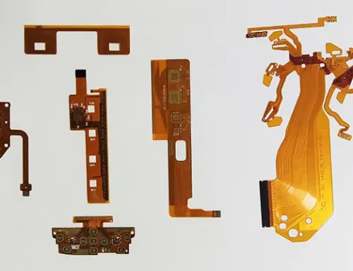
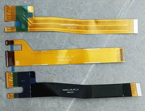
The fundamental characteristics of FPCBs are their light weight, thin profile, and ability to bend and fold. They are well-suited for three-dimensional interconnections and installations, enabling reduced installation dimensions, weight, errors, and time, while also lowering installation costs. Achieving three-dimensional interconnections is the essential feature of flexible circuits. An actual FPCB sample is shown in Figure 1.

Figure 1: FPCB Sample
Like rigid printed circuit boards (RPCBs), FPCBs are structurally classified into single-layer, double-layer, and multi-layer boards, as detailed below:
(1) Single-layer FPCB refers to a flexible board with only one conductor layer.
(2) Double-sided FPCB contains two conductor layers, with or without plated through holes (PTH).
(3) Multilayer FPCB consists of three or more conductor layers laminated together, including standard multilayer FPCB and high-density interconnect (HDI) multilayer FPCB.
Additionally, they can be categorized by material or application: – By substrate: polyimide flexible boards, polyester flexible boards, liquid crystal polymer flexible boards, etc. – By application: camera flexible boards, notebook computer flexible boards, mobile phone flexible boards, etc. Classification by structure is more appropriate as it better reflects their performance characteristics.
Special Structure FPCBs
Currently, several types of special structure FPCBs exist.
(1) Double-access Flexible Circuit Board (D-Access FPCB) or Back-Bared Flexible Circuit Board
Featuring a single layer of conductive traces, this board exposes connection pads on both sides of the PCB, enabling dual-sided assembly and connection. This is a specialized single-sided FPCB, as shown in Figure 2.

Figure 2: Double-sided Through Hole Single-sided FPCB
(2) Sculptured Flexible Circuit Board
This board features varying copper conductor thicknesses across different sections. Typically, the copper in bendable conductor areas is thinner, while the copper at edge connector terminals is thicker to enhance insertion strength, as shown in Figure 3.

Figure 3: Engraved FPCB
(3) Stiffened Flexible Circuit Board
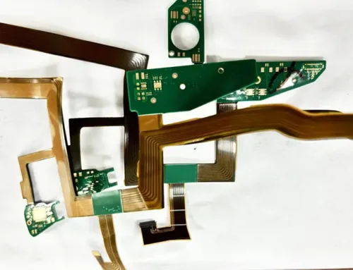
This FPCB (also known as a rigidized flexible circuit board) incorporates a stiffening plate bonded to specific areas requiring enhanced rigidity. It supports electronic components, as shown in Figure 4.

Figure 4: Reinforced FPCB
If the reinforcement plate is made of metal, it can also serve heat dissipation and shielding functions.
The reinforcement plate (stiffener) in a reinforced FPCB has absolutely no electrical connection with the circuits in the flexible areas, thus differing from rigid-flex boards.
(4) Shielded Flexible Circuit Board
To protect flexible interconnects from electromagnetic interference, a mesh shielding layer is typically added during rigid multilayer board design.
The flexible board section can utilize printed silver paste conductor layers as shielding, as shown in Figure 5. The silver paste conductor shielding layer is achieved through screen printing after the solder mask layer is completed.

Figure 5: Shielded Flexible Board
(5) Flexible Flat Cable (FFC)
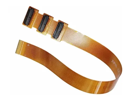
It is an electrical connection line formed by arranging multiple flat conductors at equal intervals on an insulating film. The flat conductors are copper foil. This was the earliest prototype of FPCB, replacing stranded wires to achieve electrical connections between components, as shown in Figure 6.

Figure 6: Flexible Flat Cable
(6) Flexible package carrier
A flexible package carrier integrates flexible circuits with integrated circuit (IC) packaging. This process directly mounts bare chips onto a flexible substrate (chip on film/chip on flex, COF), allowing designers to stack IC packages one atop another. This achieves maximum interconnections within minimal space.
Existing chip mounting methods on flexible circuits include tape-automated bonding structures, wire-bonding structures, and flip-chip structures, as shown in Figure 7.
")
Figure 7: Chip on Flexible Substrate (COF)
(7) Semi-Flexible PCB
This product uses epoxy glass cloth board (FR-4) as the substrate material, typically with a board thickness less than 0.30 mm, and is only suitable for static bending applications during installation. It serves as a low-cost solution for specific curved surface mounting requirements, as shown in Figure 8.

Figure 8: Semi-rigid Printed Circuit Board
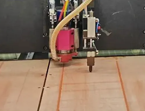
(8) Flexible heater
It utilizes polyimide and silicone rubber substrates. This bendable heater incorporates unique conductor materials and manufacturing processes, as shown in Figure 9.

Figure 9: Flexible Heater
Traditional polyimide structures tolerate 150–200 °C and perform reliably within this range, while designers engineer polyimide flexible heaters to withstand continuous operation up to 250 °C.
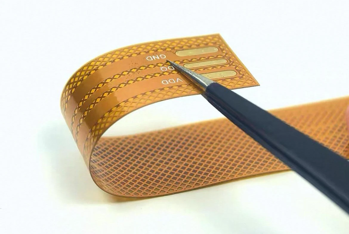
(9) Transparent FPCBs
A transparent or nearly transparent FPCB composed of a flexible substrate and conductive layers, as shown in Figure 10.

Figure 10: Transparent FPCB
Applications of transparent FPCBs include transparent heaters, transparent antennas, transparent lighting films, and transparent touch sensors. Designers commonly use polyethylene terephthalate (PET) film as the substrate for transparent FPCBs. Some transparent antennas utilize polycarbonate (PC) film or polyphenylene sulfide (PPS) film. (polyphenylene sulfide, PPS) film.
Designers commonly use indium tin oxide (ITO) as the standard transparent conductive material; however, it offers limited flexibility, transparency, and conductivity. Alternative materials include conductive polymers such as carbon nanotubes and silver nanowires.
(10) Cubic FPCBs
An FPCB that maintains its three-dimensional shape after bending and forming, as shown in Figure 11.
")
Figure 11: 3D Flexible Printed Circuit Board (FPCB)
It employs a liquid crystal polymer (LCP) substrate with excellent formability. The three-dimensional configuration enables repeated elastic operation and finds applications in LED lighting, antennas, robotics, and more.
(11) Stretchable FPCBs
This FPCB utilizes elastic, stretchable insulating films combined with stretchable conductive materials.
Elastic polymer materials include polyurethane and silicone rubber. Stretchable conductive materials employ metal gel technology to create elastic metal gel circuits, forming reliable stretchable conductor systems.
Another approach involves designing metal conductor patterns on stretchable insulating films into serpentine configurations to create stretchable FPCBs, as shown in Figure 12.

Figure 12 Stretchable FPCB
When applied to human joints, stretchable FPCBs can bend and stretch, promising a natural wearing experience.
(12) Biocompatible FPCBs
This FPCB does not cause harm to human tissue when in contact with or implanted in the body and is compatible with human physiology.
Products that remain long-term in the body’s warm, moist environment require not only extreme reliability but also biocompatibility—meaning the FPCB substrate and conductors must not corrode, decompose, or rust.
Biocompatible substrates utilize polyimide or liquid crystal polymer films; circuit conductors employ precious metals like gold or platinum, or conductive polymers and graphite.
Conclusion
The diversity of FPCBs, much like their flexible and adaptable nature, encompasses numerous types to meet market demands. Applications such as segmented LED lighting strips, solar panels, automotive seat sensors, medical guide tube circuits, aerospace and military antennas all require extra-large FPCBs exceeding 1.0 m in size. British companies have already supplied 72 m long multilayer FPCBs for industrial applications.
Rigid-flex printed circuit boards (R-FPCBs) represent another specialized category of FPCBs. Additionally, printed electronics (also termed flexible electronics or soft electronics) constitute a distinct yet related application within the broader FPCB spectrum.