FFC vs FPC: Which One Fits Your Design Best?


1. Introduction
Flexible electronics have revolutionized the design of modern devices. They are instrumental in batteries. These electronics save space and provide high-performance electrical connections. FFC (Flexible Flat Cable) and FPC (Flexible Printed Circuit) are among the most commonly used flexible interconnects.
Although they appear to be quite similar at a glance, their structures, functions, and uses vary greatly. Here, we outline the key differences between FFC and FPC, enabling you to determine which option is best for you.
2. Understanding the Basic Structures
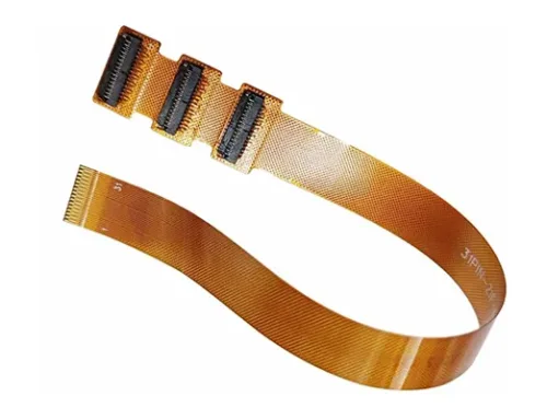
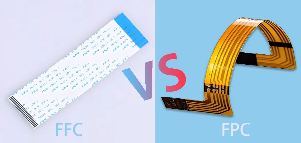
What is FFC?
FFC (Flat Flexible Cable) is a flat cable. It has many metal conductors lined up next to each other. Manufacturers produce the cable from a thin, flexible plastic film, typically made from PET plastic.
Manufacturers often use flexible electrical cables in devices such as laptops and printers. People need them for high flexibility in small spaces. I.e., Standardized pitch sizes of 0.5mm, 1.0mm, and 2.54mm; Features flat flexible cables with consistent insertion force.
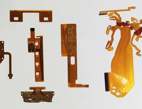
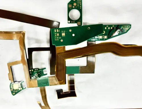
What is FPC?
A Flex PCB (FPC), also known as FPC cable, refers to a printed circuit board that engineers configure using flexible materials, including polyimide. It has one or more conductive layers, usually made of copper. These layers can be single-sided, double-sided, or multilayer.
You can make these printed circuits using various materials on flexible surfaces. You can arrange them in any layout. They meet the needs of thin and complex designs found in consumer electronics, medical devices, and cars.
3. What is the difference between FFC and FPC?
Comparison Table
| Feature | FFC | FPC |
|---|---|---|
| Structure | Flat flexible cable | Etched printed circuit |
| Material | PET, copper conductors | Polyimide, copper layers |
| Layers | Single conductor layer | Single-sided, double-sided, multilayer |
| Design Flexibility | Limited to straight paths | Fully customizable |
| Pitch Sizes | 0.5mm, 0.8mm, 1mm, 1.25mm, 2.54mm | Custom; down to 0.05mm |
| EMI Shielding | Metal foil wrapping | Shielding film + ground connection |
| Connectors | ZIF | ZIF, BTB |
| Cost | Lower | Higher, varies by complexity |
| Common Applications | Flat connections in electronics | High-performance, flexible circuit boards |
① Manufacturing Techniques
FFC is produced through stamping or lamination, where pre-manufactured flat metal conductors are laminated between PET layers. Light-based printing and chemical etching manufacture FPCs, allowing for complex circuit layouts.
② Design Flexibility & Conduction Mechanism
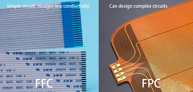
- FFC is inherently linear—the conductors run straight without the ability to cross over or create multilayered paths. Designers mostly restrict it to single-conductor layer designs. Typical pitch options include 0.5mm, 0.8mm, 1mm, 1.25mm, and 2.54mm. The shapes and lengths are limited, offering fewer personalized designs for unique device designs.
- FPC, in contrast, allows for creative and compact layout designs with intricate routing. It supports side-flex circuits. This means you can place circuits on single side, both sides, or stack them in multilayer flexible PCB setups. You can make the trace width and spacing as fine as 0.05mm to accommodate high-density applications.
③Electrical and Mechanical Performance
FPCs generally offer better performance in terms of signal integrity and thermal resistance due to the use of high-quality materials and superior design flexibility. FFCs, while simpler, are still highly effective for short, fixed routing.
④ EMI Shielding Capabilities
- FPC manages EMI shielding by using metal films on both sides. It grounds them through vias, making it efficient and low-cost.
- FFC requires you to wrap the whole cable in metal foil. Then, you must insulate it with a non-conductive layer. This is a labor-intensive process, slower to produce, and more expensive overall.
⑤ FFC FPC connector
- FFC typically uses ZIF (Zero Insertion Force) connectors.
- FPCs, by contrast, support ZIF as well as BTB (Board-to-Board) connectors, giving more options in compact or modular system design.
Details of commonly used connector manufacturers: OCN \ HRS \ KYOCERA
⑥ Cost Considerations
FFC tends to be more cost-effective due to its simpler manufacturing and materials, especially in high-volume applications. FPC can be more expensive but offers greater functional value and design freedom.
⑦ Application Differences
| FFC Applications | FPC Applications |
|---|---|
| Printers, LCDs, and laptops | Smartphones, tablets, medical devices |
| Consumer appliances | Automotive sensors and battery packs |
| Optical drives | Wearables and IoT devices |
| Internal wiring between fixed boards | Flexible antennas, curved PCB applications |
4. How to Choose Between FFC and FPC
The right choice depends on your application requirements:
- FFC flat flexible cable is an excellent choice for adding easy, low-cost flat cable connections to your design. It works well for a standard layout.
- Flexible printed circuits (FPCs) are more versatile than FFCs, offering high-density routing, and are suitable for performance-demanding applications, such as smartphones. Additionally, dimensions, power requirements, mechanical stress, and the connector’s compatibility are also important factors to consider. Consulting with a flex PCB manufacturer or flexible circuit board manufacturer early in the design process is beneficial. It can save both time and money.
5. Conclusion
Both FFC and FPC serve essential roles in modern electronics. FFC(flat flex cables) is affordable and straightforward. FPC enables advanced designs and greater tailoring.
Knowing the difference helps you make better choices. This leads to improved product performance, easier manufacturing, and lower costs.
If you are using diy flexible PCB. Understanding them can help you make better design choices. This applies to flex PCB projects and sourcing from rigid flex PCB manufacturers.
FAQ:
1. What is an FPC cable and how is it different from a rigid PCB?
An FPC (Flexible Printed Circuit) cable is a flexible electronic interconnect made from materials like polyimide or polyester. Conductive copper traces are etched onto this flexible substrate, allowing the cable to bend, fold, and twist without losing electrical performance. Unlike rigid PCBs, FPC cables are designed for tight spaces, moving parts, and lightweight applications.
2. What factors should I consider when selecting an FPC cable?
Key parameters include:
Pitch size: Ranging from 0.1 mm to 1 mm; smaller pitch suits compact devices.
Number of conductors/layers: Choose single, double-sided, or multilayer based on current load and signal requirements.
Front flip vs. back flip: Must match the connector’s mating orientation.
Bend radius & flex cycles: Dynamic applications require high-flex rated designs.
Shielding: Needed for high-speed or sensitive analog signals.
3. What types of FPC cables are available?
Common options include:
Single-sided FPCs for simple circuits
Double-sided FPCs with vias for higher routing complexity
Multilayer FPCs for dense or space-limited designs
Stiffener-supported FPCs to reinforce the connector area
Custom die-cut FPCs shaped to fit precise envelope constraints
These configurations enable optimal routing, durability, and signal integrity.
4. How do I properly connect an FPC cable to a device?
FPC cables can be connected using:
ZIF connectors (most common; tool-free and easy to assemble)
BTB connectors (great for high-speed interconnects)
Hot-bar soldering/ACF bonding (used in OLED displays and ultra-thin devices)
Adhesive-based connections (often in wearables and medical devices)
Choosing the right method depends on mechanical constraints, signal integrity requirements, and assembly equipment availability.
5. What are common FPC cable issues and how can they be repaired?
Typical issues include trace breaks, pad lifting, connector wear, and edge damage. Repair methods include:
Conductive silver ink or copper tape for broken traces
Controlled local heating to avoid pad peeling
Replacing worn ZIF connectors
Reinforcing edges with Kapton tape
While repairs help during prototyping, mass production should avoid repeated bending and improper installation to reduce failures.
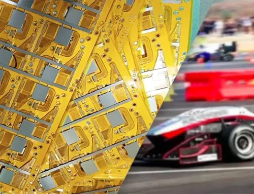
6. What industries rely on FPC cables, and when should I choose FPC over FFC?
FPC cables are widely used in consumer electronics, automotive, medical devices, industrial automation, aerospace, and defense due to their flexibility and compact design.
Choose FPC when you need:
Complex signal routing
Multiple layers
Tight bends
Customized shapes
Choose FFC for standard, low-cost, parallel conductor applications where minimal tailoring is needed.
FAQ:
1. What is the main difference between FFC and FPC?
FFC (Flat Flexible Cable) is a flat ribbon-style cable made from PET film with parallel metal conductors. It is simple, cost-effective, and commonly used for fixed, straight-line connections.
FPC (Flexible Printed Circuit) is a flexible PCB made from polyimide with etched copper traces. It supports complex layouts, multilayer routing, and fine pitch designs, making it ideal for high-density or curved electronics.
2. When should I choose FFC instead of FPC?
Choose FFC when:
Your design needs low-cost, simple, or standardized cable connections.
Routing is linear and does not require multilayer structures.
Common pitch sizes (0.5mm, 1.0mm, 2.54mm) are sufficient.
You are connecting devices like printers, laptops, LCD displays, or internal boards in fixed positions.
FFC is ideal for straightforward consumer electronics wiring where performance demands are moderate.
3. When is FPC a better choice than FFC?
Choose FPC when the application requires:
High-density routing
Complex circuit layouts
Multilayer structures (single, double, or multilayer)
Very fine pitch (down to 0.05mm)
Superior thermal resistance or signal integrity
Bending, folding, or 3D shaping
FPC is commonly used in smartphones, medical devices, wearables, automotive sensors, and curved PCBs.
4. How do FFC and FPC differ in EMI shielding?
FPC EMI shielding: Uses metal shielding films and ground vias, offering effective, compact, and efficient EMI suppression.
FFC EMI shielding: Requires wrapping the entire cable in metal foil and adding insulation afterward. This process is more labor-intensive and slower to produce.
If EMI performance is critical, FPC typically provides a more robust and scalable shielding solution.
5. What connectors are used for FFC and FPC?
FFC connectors:
Mainly use ZIF (Zero Insertion Force) connectors.
FPC connectors:
Compatible with ZIF
Also support BTB (Board-to-Board) connectors for high-speed or modular designs.
Common connector brands include OCN, HRS, and KYOCERA.
6. Which option is more cost-effective: FFC or FPC?
FFC is generally more affordable because it uses simpler materials (PET + metal conductors) and a straightforward lamination process.
FPC is more expensive due to polyimide substrates, copper etching, multilayer capabilities, and custom routing options.
However, FPC provides more functionality and design freedom, making it cost-effective for advanced or high-performance applications.