Experimental Study on Crimp Terminals for FPCB Connectors


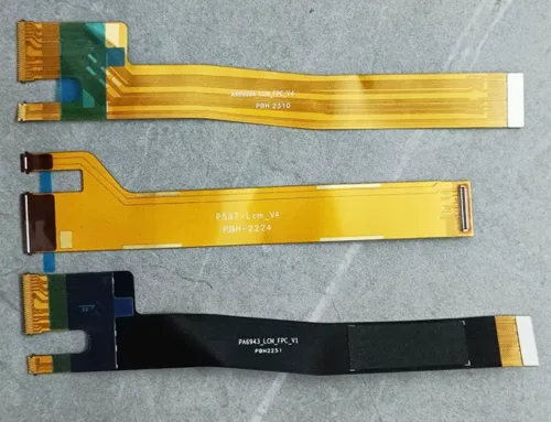
With the continuous expansion of flexible printed circuit board (FPCB) applications, certain FPCBs now serve as connectors linking functional modules. Traditional FPCB plugs are prone to wear during connector interface insertion and removal, compromising electrical connection stability.
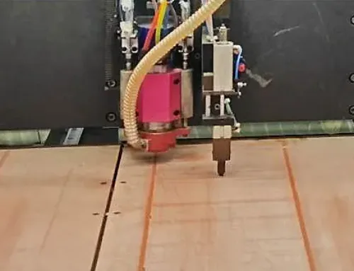
Terminal crimping technology involves the sharp tip of the connector terminal piercing through the insulating material on both sides of the FPCB plug contact via pressure. It then bends and wraps around the finger-shaped contact, hereafter called the “finger.” This action squeezes the finger to establish electrical continuity and achieve the connection, as shown in Figure 1.
This connection technology removes the need for soldering or laser welding. It avoids issues like cold solder joints, fractures, and detachment. It offers advantages including high efficiency, convenience, and safety.
After crimping the connector terminal to the FPCB finger, tool height, pressure, and crimping speed affect performance. These factors influence contact resistance, pull-out force, and surface damage.
This paper investigates how connector terminal crimping quality relates to different crimping parameters. Experiments are conducted to determine the optimal crimping parameters.

Figure 1: Structure of FPCB Finger and Connector Terminal
Experimental Section
Crimp Connection Methods for Connector Terminals and FPCB Fingers
There are two contact methods for electrical connection between the connector terminals and FPC fingers:
(1) Concave-bottomed terminal contacting the finger: The terminal’s sharp tip pierces the FPCB finger’s insulating layer. It then bends toward the back surface of the finger. This causes the bottom of the terminal to make contact with the FPCB finger through compression, establishing electrical connectivity, as shown in Figure 2(a).
(2) Connector terminal sharp edge bent to contact finger: The sharp portion of the terminal pierces the insulation layer from the back side of the FPCB finger and then bends toward the finger surface. This causes the sharp bent portion to make compression contact with the FPCB finger, establishing electrical connectivity, as shown in Figure 2(b).
As shown in Figure 2, after bending, the sharp portion of the connector terminal compresses against the concave base or curved section. This establishes conductive contact with the FPCB finger. The engineer evaluates the connection by measuring the post-crimp terminal width and height. They also measure the contact resistance between the FPCB finger and the terminal.

Figure 2: Cross section of Connector Terminal and FPCB Finger Crimp Connection
Test Materials and Equipment
(1) The connector terminals used in this test are Molex 114-94383.
(2) Flexible Copper Clad Laminate (FCCL): Polyimide (PI) film 25 μm, epoxy adhesive (AD adhesive) 25 μm, copper foil 35 μm.
(3) Instrumentation: crimping equipment, sectioning and grinding machine, metallurgical microscope, tensile testing machine, four-wire probe DC low-resistance tester.
Test Design
♦ FPCB Finger Specifications
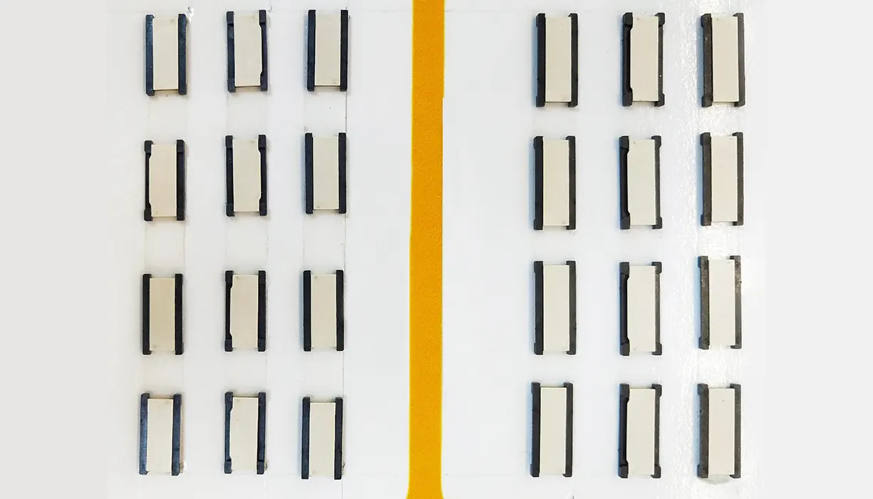
Based on connector terminal specifications and compensation standards, the width (pin) and pitch of the board-edge plug and contact fingers are as shown in Figure 3.

Figure 3: FPCB Crimp Finger Design
♦ Terminal Crimp Process Flow
Tool installation and debugging → Loading connector terminals into feeders → Adjusting tool height, pressure, and crimping speed → Positioning FPCB fingers → Debugging crimping program → Crimping → Testing.
Test Process, Results, and Analysis
Test Method
The team evaluates the quality of crimped connector terminals and FPCB fingers by inspecting post-crimp terminal height, width, contact resistance, pull-out force, and appearance. Terminal height and width after crimping affect pull-out force and contact resistance, while also influencing the degree of compression damage to FPCB fingers.
The team performs the testing using a metallurgical microscope after sectioning, as shown in Figure 2. They measure the contact resistance between the connector terminals and FPCB fingers using a low-resistance tester, as illustrated in Figure 4.

Figure 4: Connector Terminal Contact Resistance Test
Test Results and Data Analysis
♦ Testing of Terminal Height, Width, and Contact Resistance After Crimping at Different Tool Height Settings
The team varies the tool height setting, pressure, and crimping speed (see Table 1 for test parameters) and evaluates the post-crimp terminal width, height, and contact resistance.
The team simultaneously conducts cross-sectional analysis to compare damage to FPCB fingers under compression (10 test sets per configuration).

Table 1: Test Plan for Different Tool Heights, Pressures, and Speeds
(1) The trend of terminal height variation with tool height setting is shown in Figure 5.

Figure 5: Trend of Test Terminal Height Variation with Tool Setting Height
Figure 5 indicates that terminal height increases as the tool height setting rises, pressure intensifies, and the crimping speed accelerates.
When tool heights were set to 0.00 mm, 0.01 mm, and 0.02 mm, the terminal height data exhibited the smallest variation range and the most concentrated distribution.
The team selects three schemes: a minimum tool height of −0.04 mm, an intermediate height of 0.01 mm, and a maximum height of 0.04 mm. They show the cross-sections after crimping in Figure 6.

Fig 6: Cross section of FPCB finger and terminal contact under different tool height settings during crimping
Figure 6(a) shows the terminal’s sharp tip fracturing the FPCB finger; Figure 6(c) reveals a gap between the terminal’s curved section and the FPCB finger.
Figure 6(b) shows good contact between the terminal bend and the FPCB finger, with no cracking or insufficient contact issues.The terminal height data range remains relatively concentrated, meeting the requirements for optimal crimping quality. Therefore, a tool height of 0.01 mm is the optimal parameter.
(2) The trend of terminal width variation with tool setting height is shown in Figure 7.

Figure 7: Trend of Terminal Width with Variation in Tool Setting Height
Figure 7 indicates that terminal width decreases as tool height increases, pressure intensifies, and speed accelerates during crimping.
When tool heights of −0.01 mm, 0.00 mm, and 0.01 mm were set, the terminal width data exhibited the narrowest variation range and highest data concentration.
(3) The variation trend of terminal contact resistance with tool setting height is shown in Figure 8.

Figure 8: Trend of Terminal Contact Resistance with Variation in Tool Setting Height
Figure 8 indicates that contact resistance increases as tool height increases. When tool height ≤ 0.01 mm, terminal contact resistance values remain relatively concentrated.
Comparing post-crimping terminal height, width, and contact resistance reveals that tool heights between 0.00 mm and 0.01 mm represent optimal conditions.
♦ Effect of Cutting Tool Pressure Settings on Terminal Height, Width, and Contact Resistance
Based on the findings in Section 2.2.1, the tool height was fixed at 0.01 mm through selection. Measurement of changes in terminal height, width, and contact resistance tracked variations in cutting tool pressure and speed. Variable parameter settings appear in Table 2.

Table 2: Test Plan for Different Tool Pressures
Following the plan outlined in Table 2, testing examined the height, width, and contact resistance of connector terminals.
(1) The trend of terminal height variation with tool pressure is shown in Figure 9.

Figure 9: Trend of Terminal Height Variation with Tool Setting Pressure
Figure 9 indicates that terminal height decreases as tool pressure increases. When the tool pressure is set to 700 N, 800 N, and 900 N, the measured terminal height data shows the highest concentration and the smallest variation range.
(2) Figure 10 shows the trend of terminal width variation with tool pressure settings.

Figure 10: Trend of Terminal Width with Variation in Tool Setting Pressure
As shown in Figure 10, terminal width gradually increases with higher tool pressure settings and faster crimping speeds.
With tool pressure set to 700 N, 800 N, and 900 N, terminal width test data shows the highest concentration and the smallest variation range.
(3) Figure 11 shows the trend of terminal contact resistance with varying tool setting pressure.

Figure 11: Trend of Terminal Contact Resistance with Variation in Tool Setting Pressure
As shown in Figure 11, the contact resistance of crimped terminals gradually decreases with increasing tool setting pressure and faster crimping speed. When the tool setting pressure is ≥700 N, the contact resistance data for each test group exhibits similar concentration and fluctuation ranges.
Comparing the test results for terminal height, width, and contact resistance identifies the optimal tool pressure range. The optimal tool pressure range is 700 N to 900 N.
Similarly, analysis of three sets of cross-sections with minimum, intermediate, and maximum tool pressures examined the crimping condition of FPCB fingers.

Figure 12: Cross-section of contact between FPCB fingers and terminals after crimping under different tooling pressure settings
Figure 12 shows variations in the contact surfaces between terminals and FPCB fingers. No cracking, damage, or poor contact is observed in the FPCB fingers. Tool setting pressure affects the height, width, and contact resistance of crimped terminals. It does not cause cracking or poor contact in FPCB fingers. Tested contact resistance values show minimal variation between 3.1 and 3.7 mΩ.
♦ Testing the Effect of Tool Crimping Speed on Post-Crimping Terminal Height, Width, and Contact Resistance
Building on the previous tests, the tool height was fixed at 0.01 mm and the pressure at 800 N. The evaluation examined how varying crimping speed affects terminal height, width, and contact resistance. Table 3 details the test plan.

Table 3: Test Plan for Different Tool Speeds
(1) Figure 13 shows the trend of terminal height variation with tool crimping speed.

Figure 13: Trend of Terminal Height Variation with Tool Crimping Speed
As shown in Figure 13, with constant tool height and pressure, changing crimping speed shows no clear trend. Terminal height data exhibit no discernible pattern. Tested values fluctuated around 0.554 mm, indicating that changing the tool crimping speed has a negligible effect on connector terminal height.
(2) Figure 14 shows the variation trend of terminal width with tool crimping speed.

Figure 14: Trend of Terminal Height Variation with Tool Crimping Speed
As shown in Figure 14, with constant tool height and pressure, changing crimping speed shows no clear trend. Terminal width measurements display no discernible pattern. Test data fluctuates around 1.24 mm, indicating that changing the tool speed has a negligible effect on connector terminal width.
(3) Figure 15 shows the trend of terminal contact resistance with tool crimping speed.

Figure 15: Trend of Terminal Contact Resistance with Tool Pressing Speed
As shown in Figure 15, with constant tool height and pressure, changing crimping speed shows no clear trend. Terminal contact resistance data display no discernible pattern. Test values fluctuate around 3.25 mΩ, indicating that changing the tool crimping speed has a negligible effect on connector terminal contact resistance.
Conclusions
Analysis and testing of terminal crimping using FPCB fingers examined tool height, pressure, and crimping speed. These factors affect post-crimp terminal height, width, and contact resistance. The analysis leads to the following conclusions:
(1) The order of influence of crimping parameters on quality is: tool setting height > pressure ≥ crimping speed.
Tool setting height controls terminal height, width, and contact resistance, determining whether crimping is fractured, proper, or incomplete.
The team finds that tool setting pressure affects crimping quality to some extent but has minimal influence on crimping damage and resistance values. They select the appropriate tool pressure based on the parameters of the crimping equipment.
Evaluation shows that tool crimping speed affects crimping quality the least and does not significantly influence it. In practical operations, they adjust it according to processing efficiency.
(2) During crimping, the sharp edges of the terminal pierce the FPCB insulation layer. The quality of crimping the FPCB fingers correlates with tool height and tool pressure.
Prior to crimping operations, test the tool height and tool pressure settings. Select the optimal combination of connector terminal crimping parameters for processing to ensure final terminal crimping quality.