What Are the Best Methods to Improve PCB Micro-Drill Performance on Flex Boards?


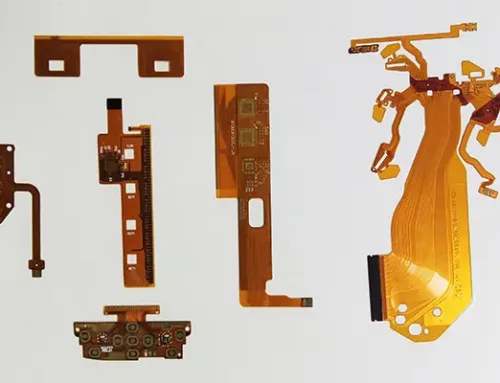
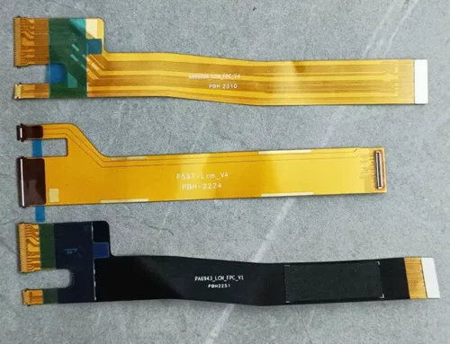
Manufacturers produce Flexible Printed Circuit Boards (FPCBs), commonly referred to as flexible circuit boards, as highly reliable printed circuit boards with exceptional flexibility, using polyimide or polyester film as the substrate material.
Compared to rigid circuit boards, flexible boards offer inherent flexibility, ease of bending, lightweight properties, and thin profile advantages.
Structurally, manufacturers form flexible boards by bonding a flexible copper-clad laminate (FCCL) with a flexible insulating layer using an adhesive (glue) and then laminating them together.
These printed circuits use flexible insulating substrates, providing numerous advantages not found in rigid printed circuit boards.
Advantages and Applications of FPCBs
For instance, designers can freely bend, roll, or fold them, enabling flexible spatial arrangements according to layout requirements. They can move and expand/contract freely in three-dimensional space, achieving integrated component assembly and wire connections.
FPCBs significantly reduce the size of electronic products, meeting the industry’s demand for high-density, miniaturized, and highly reliable devices. Consequently, FPCBs are widely used in aerospace, military, mobile communications, laptops, computer peripherals, PDAs, digital cameras, and other fields or products.
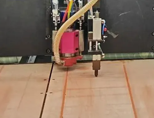
Micro-Hole Drilling in FPCB Manufacturing
Numerous methods exist for drilling small holes in workpieces. Among various micro-hole processing techniques, mechanical drilling remains relatively unaffected by workpiece characteristics, facilitates thermal deformation cutting, and reduces post-drilling finishing processes.
Compared to laser drilling, mechanical drilling retains distinct advantages in micro-hole quality, through-hole processing, and deep-hole machining.
High-speed CNC drilling machines have greatly improved the efficiency of mechanical drilling. The application of mechanical drilling in the field of ultra-fine micro-hole drilling will become increasingly widespread, and therefore remains a hot research topic in the field of micro-hole drilling technology.
This paper takes the rigid-flexible board provided by the customer as the research object, optimizes the geometric parameters of the PCB micro-drill, and draws relevant conclusions, thereby providing a theoretical basis for the engineering design of micro-drills.
Introduction to FPC Materials
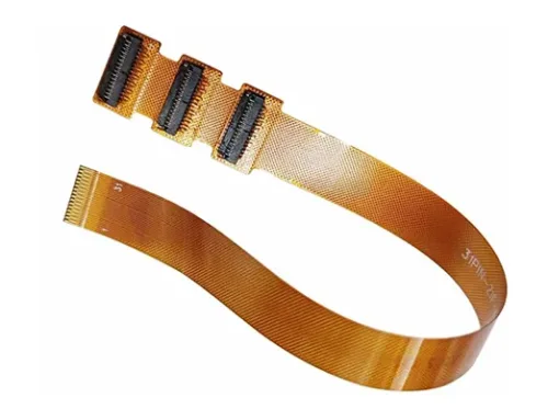
Flexible printed circuit boards are categorized into single-sided, double-sided, and multilayer types, primarily utilizing polyimide-clad copper (PI-clad copper) as the substrate material.
Polyimide (PI) film stands as one of the most critical film materials in FCCL manufacturing, accounting for the largest proportion among all film substrates used in FCCL.
This material exhibits high thermal resistance and excellent dimensional stability. Manufacturers laminate it with a cover film that provides both mechanical protection and superior electrical insulation, forming the final product.
Board Structure and Conductor Formation
The surface and inner layer conductors of double-sided and multilayer printed circuit boards achieve electrical connection between inner and outer layer circuits through metallization.
- Single-sided boards: Utilize single-sided PI-clad copper plate material. After completing the circuit, manufacturers apply a protective film to create a flexible circuit board with only a single conductor layer.
- Double-sided boards: Standard double-sided boards utilize double-sided PI-clad laminate material. After completing circuits on both sides, manufacturers apply a protective film to each surface, creating a circuit board with dual conductive layers.
- Substrate-derived single-sided boards: Employ pure copper foil material. During circuit fabrication, manufacturers sequentially apply a protective film to both surfaces, producing a board with a single conductive layer and exposed conductors on both sides.
- Substrate-based double-sided boards: Created by laminating two single-sided PI-clad boards with bonding adhesive featuring windows at specific locations. This produces a double-sided conductor board with locally bonded and locally separated layers, achieving high flex performance in the separated zones.
- Multilayer boards: Utilize single-sided PI laminate and adhesive as base materials. Using a process similar to double-sided board formation, manufacturers laminate multiple layers to create a circuit board with a multi-layer conductor structure. This allows for the design of localized layered structures to achieve high flexibility.
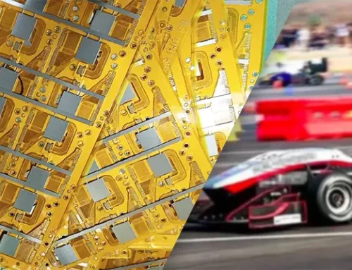
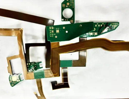
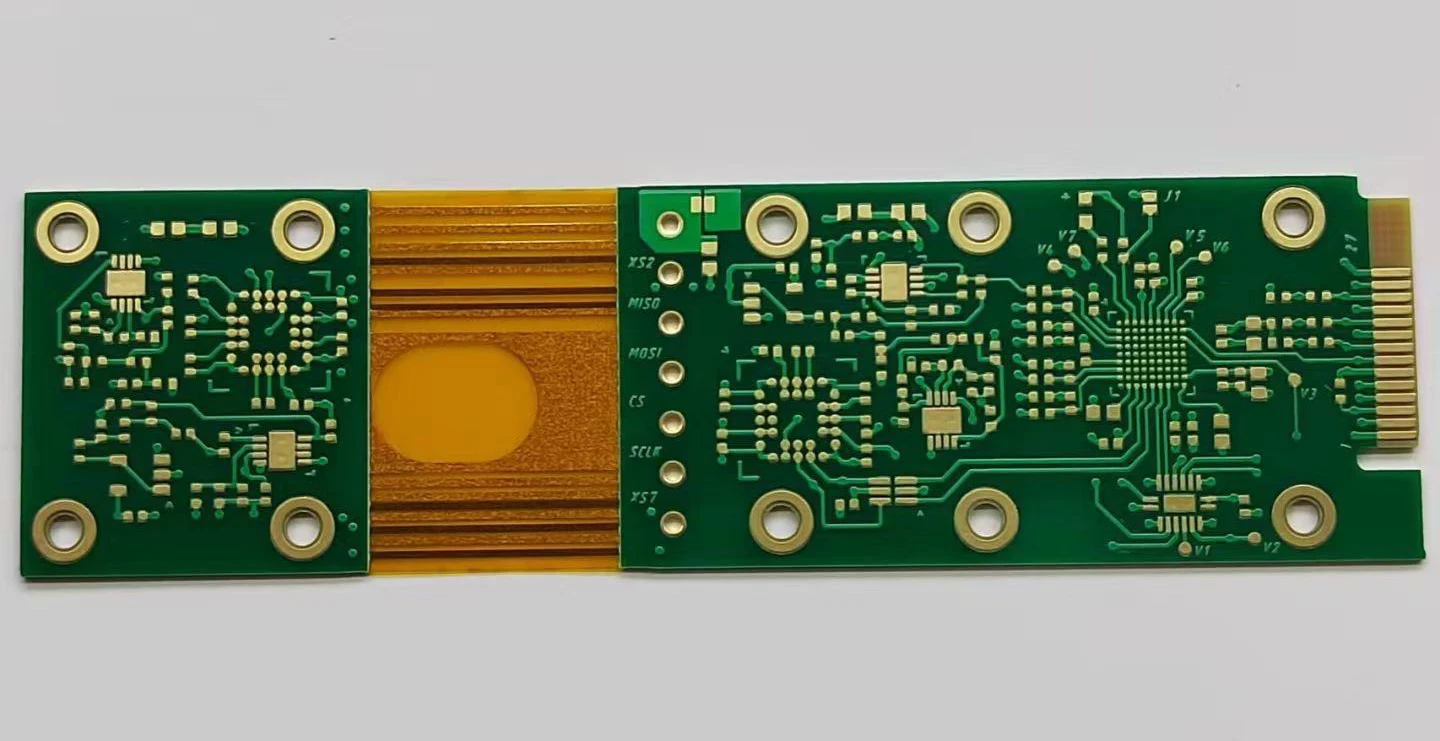
Rigid-flex boards combine the flexibility of flexible boards with the structural support of rigid boards to form a versatile circuit board.
Selection Principles for PCB Drilling
Rigid-flex boards feature complex structures, determining optimal drilling parameters crucial for achieving high-quality hole walls.
To prevent nailheading in inner-layer copper rings and flexible substrates, sharp drill bits must be selected first.
For high-volume PCB production or boards with numerous holes, drill bits should be replaced promptly after drilling a specified number of holes.
Drill speed and feed rate are the most critical process parameters: excessively slow feed causes rapid temperature rise and excessive drill sludge; conversely, too fast feed risks drill breakage, adhesive layer adhesion, and tearing or pinheading of the substrate layer.
Secondly, select the drilling machine and optimize drilling parameters based on board thickness and minimum hole diameter. For small holes, a higher rotational speed generally yields better drilling quality.
Simultaneously, the selection of cover plates and spacers is critical. High-quality cover plates and spacers not only protect the board surface but also facilitate effective heat dissipation.
To prevent severe burring during drilling, use aluminum foil sheets or epoxy phenolic boards for spacers and avoid paper spacers.
During deburring, paper pads can tear or damage hole edges, complicating subsequent processes and compromising board quality.
Testing confirms that PCB drill contamination levels and thickness increase with rising drilling temperatures, accelerating above the resin’s glass transition temperature.
Consequently, some manufacturers have experimented with cryogenic drilling—reducing board temperatures to minimize contamination.
Test Results Before FPCB Micro-HOLE Drilling Optimization
Table 1 shows the processing parameters at the customer site, and Figure 1 displays the test results obtained there.

Table 1: Machining Parameters

Figure 1: Post-Electroplating Hole Wall Inspection Image
On-site analysis revealed the following:
(1) Post-plating, burrs formed on the hole walls, primarily concentrated near the substrate layer. Single-layer hole walls exhibited fewer burrs compared to double-layer ones.s;
(2) Post-plating hole wall perpendicularity was slightly suboptimal;
(3) Regarding hole wall precision, overall cross-section analysis showed no internal quality anomalies. Both drill bit models produced holes without tearing the inner layer cover film.
The above processing failed to meet the customer’s precision requirements, necessitating drill bit re-optimization.
FPCB Micro-HOLE Drilling Optimization and Test Results
(1) Reducing the drill’s helix angle
This optimization further increases the internal flute space based on previous designs to reduce heat generation during drilling, resulting in improved hole wall quality.
(2) Reducing the drill’s ligament width
Ligament width directly impacts hole wall roughness. A wider ligament increases the contact area between the drill and hole wall during drilling, leading to greater heat generation and directly compromising hole wall quality. Reducing the ligament width enhances hole wall quality.
Optimized test data (Tables 2, 3, 4, and 5) demonstrate improved hole wall quality and enhanced positional accuracy.

Table 2 Hole Location Accuracy Statistics

Table 3 Hole Wall Precision Statistics

Table 4 A129FP⌀ 0.30–5.0 Hole Wall Precision

Table 5 A129FP ⌀0.35–5.5 Hole Wall Precision
The optimized results significantly outperformed the pre-optimization tests in the following aspects:
(1) Wear condition: Both drill bits exhibited normal wear patterns.
(2) The holes concentrated within a narrow range, achieving a position accuracy of 3σ + average ≤ 40 μm, which is well below 60 μm. Individual max values reached approximately 80μm, achieving CPK ≥ 2.5.
(3) The hole walls exhibited no internal anomalies when examining the overall cross-section. Both drill bit models produced holes with intact inner coating films and relatively straight wall entrances.
(4) Hole wall roughness < 25μm, pinhead < 150%. The optimized A129FP ⌀0.30 – 5.0 and A129FP ⌀0.35 – 5.5 meet customer requirements.
Conclusion
Researchers conducted drilling tests on a highly demanded rigid-flex board material in the electronics industry and optimized the geometric parameters of the FPCB micro-hole drilling.
Results demonstrate that the optimized FPCB micro-hole drilling significantly improves hole wall precision and hole position accuracy, meeting customer requirements and providing a theoretical basis for micro-drill engineering design.