Flexible PCB: Features, Design Guide, Applications, and Benefits


Flexible Printed Circuit (FPC) Overview
Key Characteristic
Flexible PCBs are defined by a combination of mechanical adaptability and reliable electrical performance that enables advanced product design.
Their core features include excellent flexibility for bending, folding, or dynamic movement, a thin and lightweight construction that supports compact and space-constrained assemblies, and high routing density for complex signal interconnections.
Flexible PCBs also provide strong resistance to vibration, shock, and repeated mechanical stress, along with good thermal stability and chemical resistance.
These features make flexible PCBs ideal for applications requiring high reliability, reduced assembly complexity, and improved design freedom in modern electronic systems. Their key characteristics include:
1) Flexibility.
This is the most significant advantage of FPC. By bending and folding, FPC enables convenient wiring or three-dimensional assembly in space. As long as the permissible bending radius is not exceeded, FPC can withstand thousands to tens of thousands of flex cycles without damage.
2) Compact size.
Due to design differences, FPC conductors are thinner and flatter than cables used in component interconnections, reducing wire dimensions. The lightweight, flexible conductor material enables more compact and rational overall device structures. Compared to rigid PCBs, space savings exceed 60%.
3) Lightweight.
The material composition of FPC inherently results in a lightweight product. Within the same volume, compared to cable wires with equivalent current-carrying capacity, FPC can reduce weight by up to 70%. Compared to rigid PCBs, weight reduction can reach up to 90%.
4) Elimination of installation errors.
Using cable wires for installation and wiring is prone to misconnections during installation or maintenance, often leading to rework or time wasted troubleshooting issues.
FPCs eliminate this issue. Once design drawings are verified and approved, manufactured products consistently meet specifications, preventing wiring errors. Using FPCs also eliminates cable clutter, providing equipment with a clean appearance.
5) Enhanced reliability.
FPC connections enable routing across X, Y, and Z planes, reducing interconnections and boosting overall system reliability. This also facilitates fault diagnosis.
6) Controllable electrical parameters.
Unlike cable wires, FPC allows design control over parameters such as line width, line spacing, line thickness, dielectric thickness, and dielectric constant.
This enables precise control over component characteristics like capacitance, inductance, characteristic impedance, delay, and attenuation—features difficult to achieve with cable wires.
7) Reduced total cost.
Utilizing low-cost FPCs lowers overall equipment expenses. FPCs eliminate the need for multiple rigid boards and extensive cable wiring combinations, often requiring only a single flexible board for replacement.
FPCs enable integrated assembly, eliminating wiring connection errors, reducing rework, and improving efficiency.
Additionally, FPCs simplify structural design by allowing direct adhesion to structural components, reducing costs associated with wire clamps and fasteners.
Applications of Flexible Printed Circuits
Flexible printed circuits find extensive applications across civilian and military sectors, with specific examples including:
1) Commercial electronics.
Examples include: video recorders, camcorders, cassette recorders, CD players, cameras, programmable telephones, fax machines, personal computers, word processors, copiers, washing machines, electric cookers, air conditioners, automobiles, electronic rangefinders, desktop computers, etc.
2) Military and aerospace sectors.
Examples include: aircraft black boxes, aircraft fuel controllers, accelerometers, anti-tank missiles, laser gyroscopes, radar altimeters, satellites, torpedoes, infrared detectors, space shuttle control systems, parachute vest launchers, etc.
3) Medical device sector.
Examples include: blood analyzers, defibrillators, hearing aids, drug infusion pumps, bone conduction sensors, nerve stimulators, MRI scanners, pacemakers, shielding devices, and ultrasound detectors.
Design Approach for Flexible Boards
Flexible board design encompasses three components: component selection, structural design, and electrical circuit layout.
If we liken a flexible board to a human, component selection serves as its hands, feet, and eyes—the external interface enabling interaction with the outside world.
Structural design is the torso, serving as the robust backbone of the flexible PCB; Electrical circuit design is the brain, governing the very essence of the flexible PCB.
Though their roles are distinct, each is indispensable. They must complement one another to complete the final flexible PCB design, meeting demands for high-speed, RF assembly, and electrical performance.
Structural Design Requirements for Flexible Boards
The structural design of flexible printed circuit boards determines the available space for electrical circuit layout and whether the product’s physical structure can meet mechanical and environmental requirements.
As the solid foundation of flexible PCBs, the design process must account for requirements such as bending radius, mounting positions, and non-routable areas.
Structural design must fully consider the physical reliability of flexible PCBs in conjunction with the mechanical and environmental demands of the product application.
Electrical Circuit Design Requirements for Flexible Boards
The electrical circuit design of flexible printed circuit boards is the lifeblood or soul of the board, representing the most critical aspect of its design.
The basis for electrical circuit design in flexible printed circuit boards stems from wiring relationship tables and QJ 3103-99 “Printed Circuit Board Design Specifications.”
Before commencing electrical circuit design, thoroughly analyze the product’s wiring relationships.
Identify the signals in the product’s wiring table—whether they are digital or analog signals, differential signals or power signals—and clarify the requirements for each signal type.
Only by understanding the characteristics of each signal type can the product’s true electrical performance requirements be met.
Design Methods for Flexible Boards
Component Selection Methods and Examples for Flexible Boards
Select the locking method based on the components at the user’s equipment end, choosing the corresponding locking method to meet the locking requirements as much as possible.
This prevents issues such as connector disconnection and signal interruption during the use of flexible printed boards.
♦ Assembly Method and Orientation Considerations
Assembly method selection: Determine the assembly method and orientation of connectors and PCBs based on the equipment system’s spatial structure and wiring relationships.
Examples include straight-insert PCB, angled-insert PCB, straddle-mount, and surface-mount types.
For future PCB design considerations, through-hole soldering is generally preferred.
Compared to surface-mount soldering, through-hole soldering ensures higher post-soldering reliability.
♦ Pin Arrangement and Component Standardization
Pin arrangement options: Component pin layouts vary significantly.
For example, the J30J connector offers N-type (straight-through, pin pitch 2.54mm × 2.54mm), N-J type (straight-through, pin pitch 1.27mm × 2.54mm), and W-J type (angled, pin pitch 2.54mm × 2.54mm). 54mm), W-type (angled, 2.54mm × 2.54mm), and W-J-type (angled, 1.27mm × 2.54mm).
Generally, wider pin arrangements are preferred, but spatial constraints must also be considered.
The selection of the above components ultimately forms a specific model of electronic components. Components should prioritize standard models to avoid design cycle and production cycle delays caused by model changes.

Figure 1 Selection of Scheme 1

Figure 2 Selection of Scheme 2
♦ Impact of Connector Selection on Structural Reliability
Differences in component assembly methods and mounting directions on flexible boards affect both the structural design and electrical circuit design of the flexible board.
As illustrated in the comparison between positions 1 and 2 in Figures 1 and 2 below: – Position 1 in Figure 1 uses a through-hole PCB connector mounted on the bottom surface. – Position 2 in Figure 1 uses a bent-pin connector mounted on the surface.
The connector selection ultimately impacts the structural integrity and performance of the flexible board.

Figure 3. Comparison of selection between Scheme 1 and Scheme 2
Through equipment assembly, it is evident that the selection in Figure 1 presents multiple potential performance hazards.
Due to spatial constraints at position 1 in Figure 1 and the required bending, using a straight-through PCB assembly for components necessitates a 90-degree bend of the flexible board after assembly for device integration. This requires permanent forming, making fatigue damage likely.
The device’s mounting surface constrains position 2 in Figure 1. Since the mating end on the device is positioned far from the center, bottom-side mounting is highly likely to cause interference between the flexible PCB and other device structures, ultimately preventing assembly.
Flexible Board Structural Design Methods and Examples
After selecting components for the flexible board, preliminary structural planning can be conducted based on the product’s wiring relationships and system equipment. This planning should address the following three aspects:
1) Examine the structural characteristics of the product equipment.
Begin with an overall structural plan for the flexible printed circuit board, clearly defining usable and unusable areas. Avoid unusable areas as much as possible.
2) Defining Wiring Relationships and Routing Priorities
Understand the wiring relationships of the flexible PCB, defining routing requirements between each component.
For two associated components, prioritize direct structural connection routing to minimize additional design traces.
Simultaneously, simplify components without wiring relationships to reduce or eliminate routing structures.
3) Refine details further.
For flexible PCBs with numerous components and complex wiring, incorporate mounting retention positions during structural design to enhance reliability.
Additionally, based on the assembly and soldering methods of selected components, consider whether rigid zones are needed as intermediate transfer points between surface-mount solder pads.
4) Optimizing Flex PCB Structural Layout
During flexible PCB structural design, avoid overlapping component exit points with other routing paths whenever possible. This reduces design complexity and manufacturing costs while improving manufacturability.
For example, a flexible PCB with five components mounted on a device features a wiring relationship where one component connects to multiple others. Most components are J63A straddle-type surface mounts with compact pin layouts.
Based on the above characteristics, after observing the positions and spatial structures of various mating components on the product’s supporting equipment, the model of flexible printed circuit board components was selected.
Concurrently, the structural layout of the flexible printed circuit board commenced.
Since surface-mount components’ traces are confined to a single layer, a transfer zone was designed. Considering the product’s structural fixation requirements, this transfer zone was designated as a fixed area.
Additional mounting tabs were added elsewhere, enhancing product reliability while reducing the number of layers required for electrical circuit design.
The final 5-head flexible PCB structural design is shown in Figure 4.

Figure 4.5 Flexible plate structure design
Flexible PCB Electrical Circuit Design Methodology and Example
Before designing the electrical circuits for a flexible printed circuit board, the product wiring diagram must be thoroughly understood. Key questions to clarify include:
1) What signals are present in the product?
Confirm the types of signals processed by the product based on the pin signal definitions in the wiring diagram or through communication with the user.
2) What are the requirements for these signals?
Determine the specific requirements for the signals processed by the product based on the pin signal specifications in the wiring diagram or through communication with the user. This includes whether differential signaling is required, impedance matching needs, signal overcurrent limits, and voltage drop requirements for power signals.
3) Define routing design rules.
After clarifying the signal types and requirements in the first two steps, confirm the trace width, spacing, and copper thickness based on QJ3103-99 “Printed Circuit Board Design Specifications.” Customize design rules considering derating levels, then proceed with electrical routing design.
4) Laminate Design for Flexible Printed Circuit Boards.
Since flexible PCBs feature irregular routing structures tailored to equipment spatial constraints, their laminate configuration must be determined based on the three-dimensional layout. This ensures the manufactured flexible PCB meets actual assembly requirements.
Taking the electrical circuit design of a 5-head flexible PCB as an example, the product’s main contact points include power signals, standard analog signals, and ground signals:
– Standard analog signals require a maximum current of 0.2A;
– Power signals require a maximum current of 1.3A with the lowest possible conduction voltage drop;
– Ground signals connect to the chassis ground.
Based on QJ3103-99 standards and the flexible board’s structural dimensions, the trace design specifies: – General analog signal trace width: 10 mil – Power signal trace width: 80 mil – Copper thickness: 1 oz Calculations confirm the minimum power voltage drop is 0.3Ω.
Due to routing sequence constraints, the flexible PCB employs a layered design: Top layer: J30J (spanning surface-mount components) Middle layer: J63A(1) (spanning surface-mount components) Bottom layer: J63A (2) layer for straddling surface-mount components, and J63A(3) layer for straddling surface-mount components.
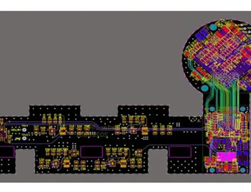
The electrical circuit design of the 5-head flexible printed circuit board is shown in the figure.

Figure 5 Signal Layer 1/2

Fig 6 Signal Layer 3/4

Figure 7 Signal Layer 5/6

Figure 8 Signal Layer 7 8
Applications
The design approach outlined above encompasses component selection, structural design, and electrical circuit layout—the three core steps in flexible printed circuit board design. However, not all flexible PCB designs strictly follow this three-step process.
Flexible PCB product design is always user-input driven, potentially encountering the following scenarios:
1) Component models are finalized, and the flexible PCB structure is determined.
At this stage, only the final step is required: confirming wiring relationships, clarifying routing rules, and executing electrical circuit design.
2) Component types are confirmed.
Steps two and three must proceed: first, establish the 3D structural layout of the flexible PCB based on the product/equipment system architecture, then perform electrical circuit design on this foundation.
3) The flexible PCB structure is confirmed.
At this stage, it is necessary to re-verify whether component selection is required or if pre-selected components match the structure. If requirements are not met, adjustments should be made promptly. Electrical circuit design follows last.
4) No clarity on any aspect.
This requires sequentially executing the three-step process, systematically addressing issues from component selection to electrical design to ultimately deliver a flawless final product.
In summary, all these scenarios are driven by user input and aim to fulfill product design requirements. They ensure thorough consideration and perfection across component selection, structural layout, and electrical design. From a design perspective, the assembly, debugging, and mechanical testing of the product must be thoroughly understood.
Conclusion
Flexible printed circuit board (FPC) design constitutes a comprehensive system spanning both structural and electrical aspects.
Designers must simultaneously consider mechanical, electrical, and other critical dimensions while mastering the application of 3D structural design software and electrical circuit design tools.
Practice makes perfect. While mastering design techniques is essential, designers must also learn from experiences gained during actual product development.
Continuously refining design methodologies will mature FPC design approaches, enabling the creation of flawless products that meet both mechanical and electrical performance requirements.