How to Roll-to-roll flex PCB manufacturing?


Flexible electronics have moved from niche to mainstream. Wearable devices, foldable displays, medical sensors, automotive interiors, and IoT modules are all driving sustained demand for high-volume, thin, lightweight, and mechanically flexible circuits.
According to multiple industry analyses, the global flexible electronics market is growing at 15–20% CAGR, with volume demand concentrated in consumer electronics and healthcare.
Traditional sheet-based (S2S) flex PCB processing, while mature and precise, becomes a scalability bottleneck when monthly demand reaches hundreds of thousands or millions of units. Handling losses, batch changeover times, and panel-level inefficiencies limit throughput and increase the cost per unit.
This is where roll-to-roll flex PCB manufacturing becomes strategically critical.
One-sentence definition (featured snippet target):
Roll-to-roll (R2R) flex PCB manufacturing is a continuous, web-based production process where flexible copper-clad substrates are processed, patterned, finished, and rewound in roll form to achieve high throughput and low unit cost circuit fabrication.
In high-volume scenarios, the R2R flex PCB process enables:
Continuous production instead of batch processing
Superior material utilization
Lower labor and handling cost per square meter
Higher consistency for mass production

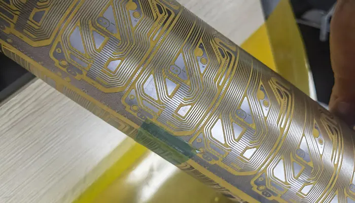
Flex PCB
What Is Roll-to-Roll (R2R) Flex PCB Manufacturing?
Definition: R2R vs Traditional PCB Processing
Conventional PCB and flex PCB production are fundamentally discrete processes. Material is cut into sheets, stacked, processed, and transferred station by station. Each transfer introduces time loss, alignment risk, and labor cost.
In contrast, R2R flex PCB manufacturing is a continuous web process. The flexible substrate is unwound from a roll, processed sequentially through multiple stations (cleaning, imaging, etching, finishing, coating), and then rewound.
This model is borrowed from industries such as film coating, printing, and lithium battery electrode production, but adapted for high-precision circuit fabrication.
Continuous Web-Based Manufacturing Explained
In an R2R line, the substrate is always in motion. Process steps are synchronized through:
Web tension control
Servo-driven rollers
Optical registration systems
Instead of “panel in – panel out,” R2R is “meter in – meter out.” The key engineering challenge is maintaining dimensional stability and registration accuracy while the material is moving.
R2R vs S2S vs Hybrid Processing
Many competitors oversimplify the discussion into “R2R or S2S.” In practice, hybrid processing is widely used in industrial production.
| Attribute | R2R Flex PCB | S2S Flex PCB | Hybrid R2R + S2S |
|---|---|---|---|
| Production mode | Continuous | Batch / discrete | Mixed |
| Throughput | Very high | Medium | High |
| Registration accuracy | Medium–high (depends on equipment) | Very high | High |
| Design complexity supported | Simple–medium | Medium–high | Medium–high |
| Typical use cases | Wearables, antennas, sensors | HDI flex, fine pitch | Display drivers, camera modules |
Hybrid processing often means:
Circuit imaging and etching done in R2R
Final outline routing, stiffener bonding, or laser cutting done in S2S
This approach balances speed with precision and is common in camera FPC, display FPC, and medical flex circuits.
How Roll-to-Roll Flex PCB Manufacturing Works (Step-by-Step)
Understanding the roll-to-roll flex PCB process flow is essential for correct design-for-manufacturing (DFM) decisions.
Substrate Preparation
The foundation of R2R processing is the flexible substrate roll.
Most commonly used materials:
| Material | Typical Thickness | Key Properties | Application Notes |
|---|---|---|---|
| Polyimide (PI) | 12.5–50 μm | High temperature resistance, dimensional stability | Standard for electronics |
| PET | 25–125 μm | Low cost, limited heat resistance | Wearables, disposable sensors |
| FCCL (PI + Cu) | Cu 9–35 μm | Direct circuit formation | Mainstream R2R material |
Width constraints:
Industrial R2R lines typically handle 250–520 mm web width, though advanced lines can reach 700 mm. Wider webs increase productivity but demand more precise tension and alignment control.
Circuit Pattern Formation
There are two mainstream approaches:
Photolithography-based imaging
This mirrors traditional flex PCB imaging, but in continuous mode. Photoresist coating, exposure, and development occur inline. Registration is achieved using optical fiducial tracking.
Printing-based alternatives
Inkjet and screen printing are used for:
Carbon circuits
Silver ink traces
Low-current applications
These methods reduce chemical processing but have lower resolution and conductivity.
Engineering challenge:
Maintaining ±20–30 μm registration accuracy while the substrate is moving is non-trivial. Web stretch, temperature drift, and roller eccentricity all affect pattern fidelity.
Etching and Circuit Definition
After imaging, copper is removed through continuous chemical etching.
Key parameters:
Etch rate uniformity across web width
Copper thickness control (typically 9–18 μm for R2R)
Undercut control at high line speeds
Because the web never stops, dwell time is controlled by line speed and etch chamber length, not by batch timing. This requires precise process tuning.
Surface Finishing
Not all surface finishes are suitable for R2R.
| Surface Finish | R2R Suitability | Reason |
|---|---|---|
| ENIG | Limited | Long dwell time, multi-step chemistry |
| Immersion Tin | Good | Simple chemistry, fast reaction |
| OSP | Very good | Inline compatible, low thickness |
| Carbon Ink | Very good | Printing-based, no wet chemistry |
High-speed lines are sensitive to oxidation and contamination, so nitrogen shielding and inline cleaning are often used.
Coverlay / Protective Layer Application
Protection is achieved by either:
Laminated coverlay film
Pre-cut PI film with adhesive is laminated under heat and pressure.
Liquid covercoat (LPI / LCP)
Applied via coating or printing, then UV/thermal cured.
In R2R, the dominant engineering issue is web tension balance. Uneven tension leads to:
Wrinkling
Bubbles
Misalignment of openings
Advanced lines use closed-loop tension control systems to keep variation within ±1–2%.
Electrical Testing and Rewinding
Before final rewinding:
Inline AOI checks trace continuity and shorts
Inline resistance monitoring flags process drift
Finished material is then rewound into master rolls or slit into smaller rolls for downstream processes such as laser cutting, stiffener bonding, or SMT.
Key Equipment Used in Roll-to-Roll Flex PCB Production
R2R is not simply “longer machines.” It is a system-level engineering investment.
Unwinding and Rewinding Systems
These manage:
Roll loading and splicing
Diameter compensation
Tension stabilization
Without stable unwinding, downstream registration becomes impossible.
Web Tension Control Systems
Typically include:
Load cells
Dancer rollers
Servo-driven nip rollers
High-end systems maintain tension variation within ±0.5–1%, which is critical for fine-line circuits.
Optical Registration and Alignment Systems
CCD cameras track fiducials in real time. The system dynamically adjusts:
Web speed
Lateral position
Exposure timing
This is the heart of dimensional accuracy in R2R flex PCB production.
Inline AOI and Thickness Monitoring
Unlike S2S, defects in R2R can propagate rapidly. Therefore:
Inline AOI detects opens, shorts, and pattern breaks
X-ray or laser thickness gauges monitor copper and coating layers
This enables closed-loop process control, not post-process inspection.
Why Equipment Cost Is High, but Unit Cost Is Low
An industrial R2R flex PCB line can cost 2–5× more than an equivalent S2S line. However:
| Factor | R2R | S2S |
|---|---|---|
| Labor per m² | Very low | Medium |
| Material utilization | High | Medium |
| Changeover time | Minimal | Significant |
| Output per hour | Very high | Medium |
At volume, the cost per circuit drops dramatically, which is why R2R dominates in:
Smartphone antennas
Wearable sensors
Display driver FPCs
Medical disposable electronics
Advantages of Roll-to-Roll Flex PCB Manufacturing
Roll-to-roll processing is not simply an alternative production method; it is an industrial scaling strategy. Its advantages become decisive when volume, consistency, and unit economics dominate design decisions.
Extremely High Production Efficiency
R2R lines operate in continuous mode, typically at 2–10 m/min depending on process complexity and resolution. This enables throughput levels that are structurally impossible for sheet-based systems.
For example:
| Parameter | R2R Line | S2S Line |
|---|---|---|
| Effective output | 2,000–6,000 m²/day | 300–800 m²/day |
| Changeover time | Minutes | 30–120 min |
| Labor per shift | 2–4 operators | 6–10 operators |
Because there is no panel loading/unloading cycle, utilization efficiency routinely exceeds 85–90%, compared with 60–70% in S2S.
Low Material Waste
In the S2S flex PCB, waste is generated by:
Panel margins
Fiducial zones
Handling damage
R2R processing eliminates most panelization losses. The material is processed edge-to-edge, and yield loss is primarily driven by process defects rather than geometric inefficiency.
Typical waste rates:
| Process | Scrap Rate |
|---|---|
| R2R flex PCB | 2–5% |
| S2S flex PCB | 8–15% |
This directly impacts cost, especially for PI + FCCL materials, where raw substrate accounts for a significant share of BOM cost.
Consistent Electrical and Dimensional Performance
Once an R2R line is tuned, it operates in a highly repeatable steady state. Temperature, chemistry, and tension are stabilized, leading to:
Narrow copper thickness distribution
Stable line width across long runs
Uniform surface finish quality
In contrast, S2S batch processing experiences process drift between panels and lots, particularly in etching and lamination.
For high-volume products such as antennas or sensor arrays, this consistency is critical for impedance control and signal repeatability.
Lower Unit Cost at High Volume
Although R2R equipment investment is high, unit cost decreases rapidly with scale.
Cost structure comparison:
| Cost Component | R2R | S2S |
|---|---|---|
| Equipment depreciation | High | Moderate |
| Labor per unit | Very low | Medium |
| Yield loss | Low | Medium |
| Unit cost @ 1M pcs | Very low | High |
At volumes above 500k–1M pcs/year, R2R typically delivers 20–40% lower unit cost compared to S2S for equivalent simple flex designs.
Ideal Fit for Standardized Designs
R2R excels where:
The design does not change frequently
Feature density is moderate
Electrical performance requirements are consistent
Best-fit product categories include:
Single-sided flex PCBs
Simple double-sided flex PCBs
LED flex strips
Sensor arrays
Wearable electronics
These products share a common trait: geometry stability and volume predictability, which aligns perfectly with R2R economics.
Limitations and Technical Challenges of R2R Flex PCB
A credible engineering evaluation must address the constraints. R2R flex PCB limitations are real and often underreported.
Layer Count Limitations
R2R is fundamentally optimized for 1–2 layer structures. Multilayer flex introduces several challenges:
Each additional layer requires lamination and precise interlayer alignment
In continuous motion, cumulative registration error becomes difficult to control
Web stretch and thermal expansion are amplified with stacked structures
In practice, 3+ layer flex PCBs are rarely produced fully in R2R mode. When multilayer is required, manufacturers typically switch to hybrid processing or pure S2S.
Via and Interconnection Constraints
Plated through holes (PTH) and microvias are core technologies in complex flex PCBs, but they are problematic in R2R.
Why PTH is difficult in R2R:
Drilling in continuous web is mechanically complex
Hole wall activation and plating require controlled dwell time
Chemical uniformity is hard to maintain at speed
Why microvias are infeasible:
Laser drilling requires precise positioning and stop control
R2R motion makes sub-50 μm accuracy extremely challenging
As a result, most R2R designs rely on:
No vias, or
Simple through connections using printed jumpers or carbon bridges
This is a major constraint compared to S2S processing.
Design Restrictions
R2R imposes stricter design rules:
Minimum trace width stability
While advanced lines can reach 50–75 μm, maintaining this consistently across kilometers of web is challenging. Many mass-production designs stay at 100–150 μm for yield stability.
Bend-zone copper stress control
Because R2R products are often thin and long, bend zones experience higher cumulative mechanical stress. Sharp corners and abrupt width transitions significantly increase crack risk.
Tolerance limitations vs S2S
Dimensional tolerance in R2R is typically ±0.1–0.2 mm, whereas S2S can achieve ±0.05 mm or better. For camera modules or connector interfaces, this difference is critical.
These factors collectively define the roll-to-roll PCB disadvantages that engineers must account for during architecture selection.
R2R vs Sheet-by-Sheet Flex PCB Manufacturing (Clear Comparison)
A direct comparison clarifies strategic positioning.
| Feature | Roll-to-Roll (R2R) | Sheet-by-Sheet (S2S) |
|---|---|---|
| Production volume | Very high | Low to medium |
| Best for | Standardized designs | Complex designs |
| Layer count | 1–2 layers | 1–10+ layers |
| Cost per unit | Low at scale | Higher |
| Equipment investment | Very high | Moderate |
| Flexibility | Low | High |
| Via capability | Limited | Full (PTH, microvia) |
| Tolerance control | Medium | High |
Interpretation:
R2R is a manufacturing efficiency weapon. S2S is a design flexibility platform. They are not competitors in the same sense; they serve different product strategies.
This is the practical reality behind R2R vs S2S flex PCB decisions.
When Should You Choose Roll-to-Roll Flex PCB Manufacturing?
Selecting R2R is not a tactical sourcing choice; it is a strategic manufacturing decision tied to product lifecycle, volume trajectory, and design stability.
From a cost–engineering perspective, R2R becomes economically rational when volume and design stability outweigh flexibility requirements.
Conditions That Favor R2R
R2R is most appropriate when annual volume is high (typically ≥300k–500k units), the layout is frozen and standardized, and the structure is single-sided or simple double-sided flex. In these cases, production efficiency and material utilization dominate cost structure, making R2R the lowest total cost option.
In consumer electronics, wearable devices, and LED lighting, product lifecycles are often short but volumes are extreme. Here, the ability of R2R lines to run continuously for days or weeks without changeover directly translates into margin protection.
Conditions That Disfavor R2R
R2R should be avoided when the product is in prototyping or frequent revision phase, or when the design requires multilayer stacks, rigid-flex transitions, tight connector tolerances, or complex via structures. These conditions favor S2S, where batch processing and discrete handling allow fine control.
From an engineering management viewpoint, forcing an R2R solution on an unstable or complex design often leads to:
Escalating NRE cost
Yield instability
Schedule risk
The correct framing is: R2R is optimized for scale, not experimentation.
Design Guidelines for R2R-Friendly Flex PCB Layouts
Most competitor content stops at process description. In reality, layout discipline determines whether R2R will succeed or fail. Designing for continuous manufacturing requires a shift in mindset.
Trace Orientation Along Web Direction
In R2R, the substrate is under constant longitudinal tension. Traces aligned with the machine direction (MD) experience significantly lower mechanical strain compared to transverse traces.
Empirical fatigue testing shows that copper traces parallel to MD can survive 2–3× more bend cycles under identical radius conditions. For dynamic applications such as wearables, this orientation strategy directly improves field reliability.
Avoid Sharp Copper Corners
Sharp corners act as stress concentrators. In continuous web handling, these become crack initiation points. Rounded corners and gradual neck-down transitions distribute stress more evenly.
From a reliability engineering perspective, replacing 90° corners with R ≥ 0.3–0.5 mm fillets can improve flex life by 30–50% in repeated bend tests.
Minimize Via Usage
Vias are process and reliability liabilities in R2R. Each via introduces:
Registration risk
Plating variability
Mechanical weak points
High-yield R2R designs typically use single-layer routing strategies, jumper traces, or printed bridges to avoid vertical interconnects.
Standardize Panel Width
R2R lines are engineered around specific web widths. Designing to standard widths (e.g. 250 mm, 300 mm, 500 mm) improves:
Material utilization
Tension stability
Slitting efficiency
Custom widths increase trim loss and reduce line efficiency. In cost-sensitive products, width standardization alone can reduce substrate waste by 5–8%.
Design for Continuous Processing
Features that require stop-start operations, localized reinforcement, or post-process manual intervention are structurally incompatible with R2R economics. The design assumption must be:
The line does not stop for your product.
If your layout requires exceptions, it is a signal that S2S may be the correct platform.
Cost Structure of Roll-to-Roll Flex PCB Manufacturing
Understanding roll to roll flex PCB cost requires looking beyond unit price and into cost architecture.
Tooling and Setup Cost
Initial setup includes:
Process tuning
Web guides and fixtures
Registration calibration
These are typically higher than S2S. NRE for R2R can be 1.5–2× higher, but it is amortized over much larger volumes.
Equipment Amortization
R2R lines represent significant capital investment. A fully integrated R2R flex line can cost USD 3–8 million, depending on width and automation level.
However, because output is high, depreciation per unit is low at scale.
| Parameter | R2R | S2S |
|---|---|---|
| CapEx | Very high | Moderate |
| Output/hour | Very high | Medium |
| Depreciation per 1k pcs | Low | Higher |
Material Utilization Efficiency
R2R’s edge-to-edge processing reduces panel margins and handling loss. In high-volume production, material utilization often reaches 95–97%, compared to 85–90% in S2S.
For PI-based FCCL, this difference alone can account for 3–6% cost reduction.
Break-Even Volume Analysis (R2R vs S2S)
A simplified model:
| Annual Volume | R2R Unit Cost | S2S Unit Cost | Preferred |
|---|---|---|---|
| 50k units | High | Medium | S2S |
| 200k units | Medium | Medium | Case-dependent |
| 500k units | Low | Medium | R2R |
| 1M+ units | Very low | High | R2R |
In most scenarios, the break-even point lies between 200k–400k units/year, depending on complexity and yield.
This is why R2R PCB pricing becomes compelling only when volume is real and sustained.
Typical Applications of Roll-to-Roll Flex PCBs
R2R adoption is driven by applications that combine volume, standardization, and moderate complexity.
Wearable Electronics
Smart bands, health monitors, and fitness trackers rely heavily on:
Single-layer flex circuits
Antenna structures
Sensor interconnects
R2R provides the cost structure required for consumer price points.
Medical Disposable Sensors
ECG patches, glucose sensors, and diagnostic strips are produced in millions of units. Here, R2R’s low unit cost and consistent quality are essential for regulatory compliance and margin control.
Flexible Lighting (LED Strips)
LED flex strips are a textbook R2R product:
Long continuous geometry
Simple double-sided structure
Extreme volume
Nearly all high-volume LED flex is produced using R2R processes.
Consumer Electronics Interconnects
Camera modules, display connections, and antenna flexes in smartphones increasingly rely on R2R for cost competitiveness.
Industrial Sensor Arrays
Pressure mats, touch sensors, and large-area sensing films benefit from R2R’s ability to produce wide, continuous circuits with uniform properties.
These applications expand the keyword footprint and reflect real industrial adoption patterns.
FAQs About Roll-to-Roll Flex PCB Manufacturing
Can R2R be used for multilayer flex PCBs?
In practice, no. True multilayer flex is poorly suited to full R2R processing due to interlayer registration and lamination challenges. Hybrid approaches may be used, but pure R2R is typically limited to 1–2 layers.
Is roll-to-roll suitable for quick-turn prototypes?
No. R2R is optimized for steady-state production. Prototyping and quick-turn iterations are structurally incompatible with R2R economics and setup requirements. S2S is the correct choice for early-stage development.
What materials are best for R2R flex PCB?
Polyimide (PI) with rolled annealed copper remains the dominant choice for electronics-grade R2R. PET is used for low-temperature, low-cost applications such as disposable sensors.
What is the minimum order quantity?
Commercially, R2R becomes viable at tens of thousands of units for simple designs, but true cost advantage is realized at hundreds of thousands or more.
How reliable is R2R compared to S2S?
When properly designed, R2R products show equal or better field reliability due to process consistency. Failures usually trace back to design incompatibility, not the process itself.
Conclusion: R2R Is a Manufacturing Strategy—Not a Universal Solution
Roll-to-roll flex PCB manufacturing excels in volume, consistency, and unit economics. It is a powerful industrial tool for standardized, high-volume products.
However, it is not a universal replacement for sheet-based processing. S2S remains indispensable for:
Complex multilayer designs
Rigid-flex structures
Tight dimensional control
Rapid iteration and prototyping
The most capable manufacturers are those who master both R2R and S2S and select the process based on engineering reality—not marketing narratives.
For product teams, the correct question is not:
“Which process is cheaper?”
but:
“Which process aligns with my design architecture, volume trajectory, and risk profile?”
If you are evaluating flex PCB process options for a new project, engaging early with a manufacturer who understands both paradigms can prevent costly redesigns and schedule delays.

