Design of Automatic Assembly Equipment for Flexible Circuit Board


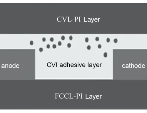
Flexible printed circuits (FPCs) are circuit boards featuring a substrate made of polyimide or polyester film, coated with conductive copper foil or conductive carbon ink [1].
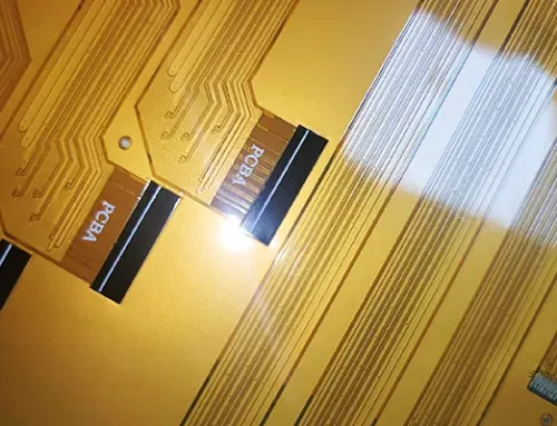
Owing to their compact size, excellent bendability, lightweight nature, and high reliability [2], they have become indispensable components in smart consumer electronics.
As electronic products like wearables, flexible displays, and smart devices evolve toward integration and miniaturization, demand for flexible circuit boards continues to grow, along with increasingly stringent assembly requirements.
Assembling these boards onto products with high speed and precision has become a major challenge for the industry.
Traditional assembly methods rely on motors paired with module lead screws or robotic arms, but their final precision and production capacity remain relatively low.
This paper presents a novel flexible circuit board assembly device. Integrating a vision system, servo system, pressure feedback system, and linear motor motion control system, it achieves high-speed, high-precision circuit board placement.
During assembly, the pressure feedback system ensures consistent pressure is applied to the product within a defined range.
This eliminates the uneven pressure caused by variations in products or materials during manual pressing, thereby preventing defective products.
Overall Equipment Design
The overall layout of the equipment was determined by considering multiple factors, including industry clients’ technical requirements, product processes, costs, and market conditions [3].
This design fully accounts for the product and flexible circuit board feeding methods within the industry. Products are supplied through the equipment’s material flow line, while circuit boards are fed via trays.
The overall equipment layout, as shown in Figure 1, primarily includes the frame enclosure assembly, product carrier flow line, gantry assembly mechanism, tray flow line, flexible circuit board hopper mechanism, vision system, suction head pressure assembly, and re-inspection mechanism.

Figure 1: Overall Layout of the Equipment
Frame Enclosure Design
The frame body consists of a welded 120 mm × 120 mm square tube structure and a high-precision marble platform.
The marble platform offers high hardness, robust texture, and excellent compressive strength.
It resists external force damage, maintains superior shape retention and flatness, ensuring the equipment’s stability and precision requirements.
The base incorporates six casters and six-foot cups, ensuring stability and ease of mobility. The protective cover, formed using sheet metal fabrication techniques, is securely fastened to the frame, delivering an aesthetically pleasing appearance.
The equipment is equipped with a safety protection system, including a three-color indicator light, safety guard door limit switches, and an emergency stop button, effectively safeguarding operator safety.
External keyboard and mouse, touchscreen, and transparent viewing windows facilitate convenient debugging.
During production operation, the equipment promptly issues fault alarms and automatically halts operation upon detecting unexpected issues or problems, enhancing production safety. The frame guard structure diagram is shown in Figure 2.

Figure 2 Rack Cover Structure Diagram
Product Carrier Flow Lines
Product carrier flow lines transport products to each workstation for positioning. The flow lines comprise three sections: the entry flow line, assembly station flow line, and re-inspection station flow line.
The entry flow line interfaces with the production line, automatically feeding products awaiting assembly into the equipment.
The assembly station flow line positions products entering the assembly station for assembly operations.
The re-inspection station flow line positions completed products for final inspection.
Each flow line segment comprises an integrated stepper motor, synchronous pulley, synchronous belt, blocking mechanism, and through-beam sensors.
Product movement is achieved by driving the synchronous pulley and belt rotation via the stepper motor.
Through-beam sensors determine the precise position and arrival status of products.
Lifting mechanisms ensure accurate product positioning. All conveyor lines feature adjustable width structures, enabling rapid adjustment to accommodate different product dimensions and facilitating quick line switching. The product carrier conveyor mechanism is illustrated in Figure 3.

Figure 3 Streamlined Mechanism Diagram of Product Carrier
Gantry Assembly Mechanism Design
The gantry assembly mechanism comprises a gantry frame, linear motor, guide rails, drag chain, linear encoder, and upper vision system, utilizing high-speed, high-precision transfer assembly system technology.
The gantry frame is assembled using marble columns and beams, providing stable support and rigidity.
This effectively minimizes vibration and deformation during motion, ensuring the equipment maintains high precision and stability at all times.
A linear motor is a device that directly converts electrical energy into linear motion without requiring intermediate conversion mechanisms [4].
Operating without mechanical contact, linear motors offer significant advantages, including high acceleration, high precision, simple structure, rapid response, and extended service life.
Linear encoders are highly precise measuring devices characterized by high resolution, sensitivity, and repeatability, achieving measurement accuracy at the nanometer level [5].
By combining the advantages of the gantry frame and linear motor, coupled with the precise feedback control of the linear encoder, the challenge of high-speed, high-precision placement has been successfully addressed. The schematic diagram of the gantry assembly mechanism is shown in Figure 4.

Figure 4 Gantry Assembly Mechanism Diagram
Tray Conveyor Line
The tray conveyor line (see Figure 5) transports trays loaded with flexible circuit boards to the pickup station and returns empty trays to the storage bin after pickup.
The conveyor line consists of an infeed conveyor, a pickup positioning conveyor, an empty tray conveyor, and a tray pickup mechanism.
The tray suction mechanism comprises a pneumatic cylinder, a linear guide, and an adjustable vacuum suction cup. This mechanism lifts full trays from the loading bin onto the conveyor or places empty trays from the conveyor into the unloading bin.
Pneumatic cylinders and linear guides are installed on both the feed conveyor and the empty tray conveyor. Cylinder actuation opens/closes the conveyors to coordinate with the tray suction mechanism’s operations.
The pick-up positioning line employs cylinders, limit blocks, and lifting plates to achieve precise tray positioning for efficient material retrieval.
This line design ensures uninterrupted flexible circuit board feeding, eliminating downtime issues inherent in traditional feeding methods and significantly enhancing equipment efficiency.

Figure 5 Streamlined Mechanism Diagram of Tray
Loading/Unloading Hopper Mechanism
The hopper employs a drawer-style loading/unloading method (see Figure 6). A lead screw lifting mechanism controls tray elevation, accommodating 20 flexible circuit boards per tray. This design greatly facilitates operator loading and unloading.
The hopper’s limit columns are adjustable. Flexible adjustment of these columns enables rapid switching between different tray types, ensuring strong compatibility.
During assembly, operators can simultaneously handle loading/unloading trays, enabling true non-stop material handling.

Figure 6 Loading and Unloading Hopper Mechanism Diagram
Vision System
The vision system (see Figure 7) employs a high-precision industrial camera, a telecentric lens, and a high-intensity light source to achieve rapid image capture and positioning [6].
The equipment captures gaps between circuit boards and products via image acquisition technology.
Image processing using the camera controller accurately measures gap dimensions and calculates required offset adjustments for the motion control system based on gap values along each edge.
The motion control system then adjusts according to these calculated offsets, achieving precise alignment.

Figure 7: Visual System Architecture Diagram
Suction Head Pressure Assembly
The suction head pressure assembly (see Figure 8) picks up flexible circuit boards and mounts them onto products via a transfer assembly system and servo pressure control system.
The equipment is equipped with three suction head pressure assemblies, enabling simultaneous placement of three flexible circuit boards to significantly enhance operational efficiency.
Pressure sensors mounted on the assembly axis provide real-time feedback on assembly pressure, ensuring precise control during placement to prevent accidental damage to the product.
Suction heads can be swapped to accommodate different flexible circuit boards, enabling rapid equipment reconfiguration.

Figure 8: Mechanism Diagram of the Suction Head Pressure Assembly
Re-inspection Module
The re-inspection module (see Figure 9) performs post-assembly photo verification to confirm that the placement accuracy of flexible circuit boards meets specifications.
Direct machine-based re-inspection eliminates manual re-checking, enhances detection accuracy, and reduces labor requirements.
The re-inspection assembly primarily consists of a servo motor, KK module, linear guide, photoelectric sensor, and vision system.
The module drives the re-inspection vision system to the product placement location for visual imaging. The camera calculates and determines whether the product placement accuracy meets specifications.

Figure 9: Mechanism Diagram of the Re-Inspection Assembly
Equipment Operating Principle and Workflow
This flexible circuit board assembly equipment utilizes a carrier conveyor line to facilitate product inflow, positioning, and outflow.
It employs a linear motor gantry assembly mechanism, vision system, and suction head pressure components to achieve high-speed, high-precision assembly of flexible cables.
Hoppers and tray conveyor lines ensure the continuous supply of flexible flat cables.
A re-inspection vision system verifies post-assembly precision compliance, rejecting non-conforming products.
By coordinating the operational sequences of various mechanisms, the equipment achieves fully automated assembly functionality.
The actions of each mechanism can run in parallel. While the tray side of the equipment is operating, the product flow line side can run simultaneously. This design significantly reduces assembly time. The specific workflow is as follows.
Equipment Tray Flow Line Side Workflow
(1) Production personnel place trays loaded with circuit boards into the hopper. The hopper transports the trays to the tray flow line feed inlet.
(2) The tray feed line opens, and the tray component picker fills the tray before lifting it to the top of the line.
(3) The feed line closes, releasing the tray onto the line.
(4) The tray containing flexible circuit boards flows through the line to the pick station line. The positioning mechanism lifts and aligns the tray.
(5) After the gantry assembly removes all components from the tray, the positioning mechanism of the pick-up line lowers, and the empty tray flows into the empty tray line.
(6) The tray suction assembly picks up the empty tray. The empty tray line opens, depositing the empty tray into the unloading bin.
(7) The equipment signals when the empty tray bin reaches capacity and removes all trays.
Equipment Product Flow Side Workflow
(1) Carriers loaded with products flow into the carrier flow line.
(2) At the entrance flow line, a barcode scanner records product information.
(3) Carriers flow into the assembly flow line, where the positioning mechanism lifts and secures them.
(4) The gantry assembly moves the suction head pressure assembly to the pick-up line to pick up flexible circuit boards from the tray.
(5) The suction head pressure assembly moves to the lower vision system to capture an image of the circuit board on the suction head.
(6) The suction head pressure assembly moves to the assembly line, where the upper vision system captures an image of the product.
(7) Guided by the vision system, the suction head pressure assembly mounts the flexible circuit board onto the product.
(8) After all products on the carrier complete flexible circuit board assembly, the positioning mechanism lowers, and the product carrier flows to the re-inspection line.
(9) The re-inspection assembly performs a final check on the assembled product, displays the inspection values on the monitor, and determines whether it passes.
(10) After re-inspection, the re-inspection conveyor line transports the assembled products to the next station on the production line.
Equipment Technical Parameters
Table 1 lists the equipment-related technical parameters.

Table 1: Equipment Technical Specifications
Control System Design
Control System Hardware Selection
The control system comprises servo drives, motion control cards, stepper motor drivers, switches, an industrial PC, power supplies, proximity sensors, and other electrical components.
The motion control card and industrial PC enable the system to sustain high-speed, high-precision motion without movement errors.
This control method features short response times, allowing real-time inspection and motion control. Proximity sensors detect carrier presence/absence and position.
Based on sensor signals, the motion control module sends pulse signals to the servo drives and stepper motor drivers, precisely controlling motor movement to achieve the entire device’s operation.
Software Design and System Commissioning
According to the motion requirements of each device component, the software employs the C# advanced programming language to develop control algorithms and data processing programs.
WinForm supports human–machine interface (HMI) development, as shown in Figure 10.
Figure 10 Software Program HMI Interface. The software program consists of nine primary modules:
- (1) Mode Selection;
- (2) Assembly Mechanism Control Program;
- (3) Loading/Unloading Bin Control Program;
- (4) Barcode Scanning and Re-inspection Station Control Program;
- (5) Carrier Flow Control Program;
- (6) Manual Debugging Interface Entry;
- (7) Feeding Flow Control Program;
- (8) I/O Input/Output Status;
- (9) IP Address and Communication Status.
When entering manual mode, perform point-to-point debugging for each workstation. Only after completing point debugging can the equipment operate automatically.
Before automatic operation, verify that all equipment components are in their initial positions.
If not, use the equipment touchscreen to control them into their initial positions.
After confirming all equipment components are in their initial positions, press the automatic operation button to initiate automated operation, enabling flexible circuit board assembly.
Key Technologies and Technical Innovations
The high-speed, high-precision transfer and assembly system operates as follows:
All transfer and assembly axes utilize linear motor systems, achieving rated accelerations exceeding 2 g and speeds up to 2 m/s while maintaining rated thrust, significantly accelerating assembly speed.
Through feedback from linear encoders, single-axis repeatability precision reaches ±2 µm, substantially enhancing assembly accuracy while ensuring high efficiency.
The high-precision visual positioning system operates as follows: a CCD vision system captures images to precisely locate products and circuit boards. Motion control system actions then execute accurate assembly with alignment precision reaching ±0.002 mm.
Abnormal Alarm: The equipment automatically triggers an alarm when it detects defective products, preventing the production of large quantities of nonconforming items.
Conclusion
This paper introduces an innovative flexible circuit board assembly device. By integrating vision positioning with linear motor motion control technology, it significantly enhances assembly precision and production efficiency.
Featuring advanced structural design, efficient workflow, and precise control methods, it effectively meets market and customer demands, pioneering a new direction for assembly equipment development in this field.