Flexible PCB Material Stack-Up: Types, Functions, and Performance


A printed circuit board (PCB) is defined as a functional board that provides point-to-point connection lines and printed component interconnections on an insulating substrate according to a predetermined design.
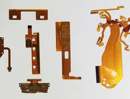
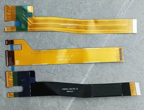
A flexible printed circuit board (FPCB) is a functional board that forms printed circuits on a bendable, flexible insulating substrate. Its basic structure is shown in Figure 1.

Figure 1 Basic Structure of FPCB
Essential materials for FPCBs include flexible insulating substrates, conductor foils (metal foils), adhesives, and cover films or solder masks.
The substrate refers to a flexible polymer film serving as the base for circuit loading and insulation isolation. It defines the primary performance characteristics of flexible circuits.
The metal foil serves as the conductive element of the flexible circuit, typically made of copper foil. Circuit patterns are formed by etching the metal foil.
The adhesive acts as the bonding medium between the substrate and the metal foil, providing the bonding strength between them.
When the substrate and metal foil are bonded directly, no adhesive is required. However, adhesives are still used for bonding the cover film to the circuit layer and for joining multi-layer flexible circuits.
The cover film serves as the surface protective layer of the FPCB, typically made from a polymer film of the same type as the substrate to maintain consistent performance.
Most current FPCB manufacturing begins with flexible copper clad laminate (FCCL).
FCCL integrates the substrate, adhesive, and metal foil through lamination, forming the base material for FPCB production.
FCCL
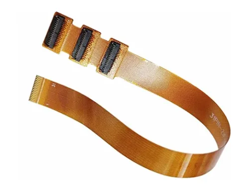
The primary raw material for FPCBs, FCCL, features a three-layer structure comprising substrate, adhesive, and metal foil, termed adhesive-bonded flexible copper clad laminate (as shown in Figure 2(a)). Alternatively, a two-layer flexible copper clad laminate exists without adhesive between substrates, termed adhesive-free flexible copper clad laminate (as shown in Figure 2(b)).
Thus, FCCL is categorized as adhesive-based or adhesive-free. Rolled FCCL is shown in Figure 2(c).
")
Figure 2 Flexible Copper Clad Laminate (FCCL)
Adhesive-free FCCL lacks an adhesive layer between substrates, allowing substrate properties to remain unaffected by adhesive influence. This enables thinner, lighter, and more flexible substrates, though the bond strength between copper foil and substrate is relatively weaker. Adhesive-free FCCL is selected for manufacturing high-performance FPCBs.
The laminating method is commonly used to manufacture adhesive-free FCCL. This involves coating or casting composite PI resin onto the roughened surface of the copper foil and the polyimide (PI) substrate. The PI substrate and copper foil are then stacked and processed through hot pressing to produce adhesive-free FCCL.
Alternatively, the sputtering method forms a conductive layer of metal ions on a film substrate through sputtering, or deposits a conductive metal layer via chemical plating. Sputtering can produce extremely thin conductive layers and is employed only when special requirements exist.
The performance of FCCL depends on the substrate, binder (adhesive), and metal foil. The thickness of FCCL is determined by the thickness of the substrate, binder (adhesive), and metal foil. Details are provided below.
Substrates
Flexible substrates are polymer films, with current primary materials including PI, polyester (PET), polyethylene naphthalate (PEN), and liquid crystal polymers (LCP).
Each substrate possesses distinct performance characteristics that define the primary properties of flexible circuits.
Performance data for common flexible substrates and fundamental differences between substrates are shown in Table 1.
Generally, the flexible substrate provides the primary physical and electrical properties of the FPCB. Without an adhesive layer, the substrate exhibits nearly all the performance characteristics of the flexible circuit.

Table 1: Performance Data of Flexible Substrates(click enlarge)
Currently, PI substrates are the most widely used, forming flexible polyimide copper-clad laminates. Their advantages include excellent electrical and mechanical properties along with high thermal resistance, though they suffer from significant moisture absorption.
Polyester substrates also see some application in flexible polyester-clad copper boards. Their advantages include good electrical and mechanical properties, low moisture absorption, and low cost. Disadvantages are poor heat resistance and limited solderability.
For high-speed, high-frequency circuits requiring superior electrical properties in substrates, options beyond modified PI include liquid crystal polymers and PTFE substrates. However, these materials see limited adoption due to challenging processing conditions and high costs.
The substrate thickness is typically available in the range of 12 to 125 μm (0.5 to 5 mil). For most flexible substrates, rigidity is proportional to thickness; thinner substrates exhibit better flexibility.
Metal Foil
Metal foil functions as the conductor in flexible circuits, and manufacturers primarily use copper foil. Additionally, designers may employ other metal foils for specialized applications—for example, aluminum foil for its lightweight and low-cost properties, or beryllium bronze for its high mechanical strength and excellent elasticity.
Manufacturers categorize copper foil into two types based on the manufacturing process: electrodeposited copper (ED) and rolled annealed copper (RA).
Manufacturers produce ED copper foil through electrolytic copper deposition, whereas they manufacture RA copper foil by rolling copper material. Compared to RA foil, ED foil offers better quality control and lower cost, whereas RA foil provides superior ductility.
Most FPCBs, therefore, use ED copper foil, whereas designers employ RA copper foil for FPCBs that require high flexibility.
Copper foil thickness varies widely, with ED copper foil ranging from 5 to 400 μm, commonly available in 35 μm and 18 μm.
Beyond thickness specifications, manufacturers also categorize copper foil by surface roughness. Specifically, for high-speed, high-frequency circuits, designers prefer foil with minimal roughness (profile) to reduce conductor signal loss.
Standard electrolytic copper foil (STD) has a roughness Rz greater than 5 μm. Reverse-treated foil (RTF) exhibits a roughness of approximately 3 μm for both rough and smooth surfaces. Ultra-low-profile copper foil (HVLP) maintains a roughness below 2 μm.
Select appropriate copper foil during FPCB design and fabrication. Table 2 lists the selected properties of copper foil and other metal foils.

Table 2: Specialized Properties of Metal Foil
However, in some FPCB manufacturing processes, designers do not use metal foils. Examples include forming copper conductors by chemically plating or electroplating copper directly onto polymer film surfaces, or printing conductive pastes onto polymer films to create conductive circuits.
Adhesive
As the bonding medium between copper foil and the substrate, manufacturers use adhesive not only for FCCL but also in FPCB manufacturing to laminate multiple layers or bond cover films.
For ease of use, the adhesive is a semi-cured film with top and bottom protective layers, as shown in Figure 3(a).
Some roll-supplied versions may feature only a single protective film, as shown in Figure 3(b);
In multi-layer flexible boards or rigid-flex circuit boards, the adhesive may coat both sides of the substrate insulating film, as illustrated in Figure 3(c).

Figure 3: Mucous Membrane
The most commonly used adhesives are epoxy resins and modified epoxy materials, which can bond dissimilar materials and exhibit good high-temperature resistance.
However, epoxy resins exhibit relative brittleness and resist flexing, although manufacturers can improve this property through modification. Meanwhile, designers widely use acrylic resins because they provide higher flex resistance.
Polyimide adhesives exhibit excellent compatibility with PI substrates and high thermal resistance, though they require elevated lamination temperatures and pressures. Table 3 summarizes the properties of the selected adhesives.

Table 3: Properties of Selected Common Adhesives(click enlarge)
Adhesive thickness in bonding films varies, typically ranging from 12 μm to 50 μm, selectable based on application requirements. When copper conductors are present in the bonding area, the adhesive must possess sufficient thickness to fill gaps between wires.
Cover Film
Cover film is a material that manufacturers apply to the surface of flexible printed circuits to protect circuit patterns while providing insulation and solder-resist functions.
Typically, the cover film material matches the substrate material—for example, PI cover film for PI substrates and PET cover film for PET substrates.
Cover film materials come in various types, as follows:
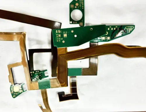
(1) Laminated Cover Film: Composed of a substrate film and a thermosetting adhesive, as shown in Figure 4. Before lamination, technicians mechanically open the “windows” that require exposure, and then they precisely position and bond the film onto the substrate surface.

Figure 4: Covering Film
(2) Photoresist-type cover film: Similar to photoresist dry film, manufacturers laminate this material onto the panel surface and then expose and develop it to form “windows.”
(3) Photoresist liquid cover coat: Manufacturers apply this liquid coating material to the PCB surface via printing or other methods, thereby forming a thin protective layer.
After exposure and development to create “windows,” the cured coating functions as the cover film.
Flexible solder resist ink also serves as a liquid cover coat. Its simple processing and low cost allow it to substitute for cover film.
Cover film performance requirements largely mirror those of the substrate, including high insulation, excellent thermal stability, strong flex and tear resistance, chemical resistance, and photosensitivity—all critical properties for FPCBs. Cover film thickness typically ranges from 12 μm to 50 μm, selectable based on application needs.
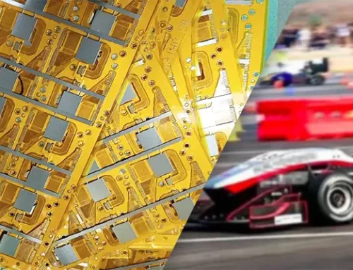
Stiffeners
FPCBs are often too thin to support connectors and certain component installations adequately. Therefore, designers apply stiffeners to non-bending areas, as shown in Figure 5.
Stiffener materials vary based on the required support strength:
– For rigidity comparable to rigid boards, epoxy glass fiber laminates are used, with greater thickness providing increased support.
For applications that require moderate strength while maintaining thinness, designers prefer PI or PET films.
If applications require additional functions—such as heat dissipation or electromagnetic shielding—alongside mechanical strength, designers can use metal foils such as aluminum or steel as stiffeners.

Figure 5: Reinforcement Plate
The bonding between the reinforcement board and the FPCB substrate film typically employs a pressure-sensitive adhesive for ease of use. For applications requiring high bonding strength, manufacturers therefore use thermosetting adhesives in conjunction with hot pressing; however, this method incurs higher costs. In addition, FPCBs do not require reinforcement boards.
Conclusion
Manufacturers use numerous materials in FPCB manufacturing; specifically, they primarily rely on insulating film substrates, metal foils, adhesives, and the combined FCCL.
Each material possesses distinct advantages and disadvantages. Material selection primarily depends on the circuit board’s installation method and end-use scenario, such as whether the FPCB undergoes static or dynamic bending, the operating environment’s temperature and humidity conditions, signal integrity requirements for circuit transmission, and installation/connection specifications.
Each material possesses distinct strengths. Selection should be based on material performance and cost considerations, ensuring optimal utilization tailored to specific requirements.