Research on the process of PI protective film for R-FPCB


Rigid-flex printed circuit boards (R-FPCBs) are composite boards formed by pressing rigid and flexible layers together, combining the characteristics of both.
With the advancement of the printed circuit board (PCB) industry, R-FPCBs—as a vital component of PCBs—have seen growing demand due to their high performance, integration capabilities, and versatility in 3D assembly.
With the rapid advancement of RFPCB technology, customer expectations for appearance quality continue to rise. Currently, during R-FPCB production operations, the flexible areas are prone to cosmetic defects, including pitting, prepreg powder residue, resin overflow, cracking, and contamination, resulting in high scrap rates.
This paper investigates the manufacturing process of polyimide (PI) protective films and the structure of RFPCBs to identify a production method that mitigates these cosmetic defects.
Solution Design
To enhance the reliability and cosmetic quality of flexible areas during R-FPCB manufacturing, this study proposes a process solution involving the application of a PI protective film onto the cover film surface.
This method aims to prevent damage or contamination of flexible areas caused by PP powder, adhesive overflow, and chemical solutions. As a result, it improves product consistency and yield rates.
This paper will outline the R&D rationale, experimental design, and material comparisons, while validating and summarizing the feasibility of the PI protective film process.
Development Approach
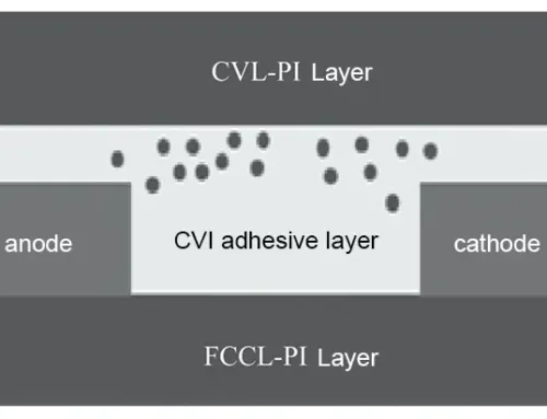
A PI protective film is applied to the surface of the cover film in the flexible zone. This film blocks prepreg powder and resin overflow, protects the flexible area from compression damage and chemical contamination, and is removed along with the cover film during lamination. The PI protective film is used to construct the R-FPCB laminate, as shown in Figure 1.
For multi-layer flexible structures, apply the PI protective film only to the outermost flexible layer.
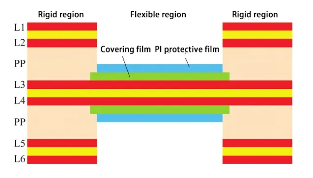
Figure 1. Fabrication of R-FPCB stack-up using PI protective film
Experimental Design
Phase 1 Process Research
(1) PI Protective Film Alignment Mark Design for Flexible Layers
When applying the PI protective film to the cover film surface, design PI protective film etching alignment mark lines on the flexible layer (matching the cover film mark lines). These mark lines serve for alignment during PI protective film lamination and for detecting misalignment.
(2) PI Protective Film Application Area Reduction for Rigid–Flexible Separation
Design the PI protective film application area 0.3 mm smaller on each side than the flexible zone to prevent lamination overlap into the rigid zone.
(3) Comparison and Validation of PI Film Application Methods
Three PI film application methods exist: pre-browning application, pre-browning application + rapid pressing of PI film, and post-browning application. We must test the pre-browning application for potential issues, such as PI film detachment during browning, chemical solution leakage, or residue buildup. Results will determine whether to adopt the post-browning application process.
(4) Lamination Applicability and Removability Verification of PI Protective Film
As the PI protective film is a low-viscosity material, verify its ease of application during lamination. Use a heating pad during operation and confirm whether it detaches easily after bonding.
(5) PP Milling Strategy and Rivet Hole Preparation Near PI Protective Film
The PP near the PI protective film does not require complete milling or inward retraction. Utilize PP to fill height differences between rigid and flexible zones. Only mechanically mill a groove along the rigid-flex edge to facilitate subsequent cover opening. Additionally, when milling PP for rivet holes, drill holes to facilitate the positioning of the rivets.
(6) PI Protective Film Peeling and Residue Inspection After Cover Opening
After opening the cover, simultaneously peel off the PI protective film. Verify whether the film peels off easily and if any issues, such as adhesive residue or peeling, occur.
(7) PI Protective Film Application and Removal Inspection
After applying and removing the PI protective film, we verify whether any areas were missed during application or removal and check if such defects can be visually identified.
(8) Large-Cavity Test Board Design for PI Film Performance Verification
The test board employs a large-cavity thin cover design to facilitate more intuitive verification of PI protective film performance.
(9) Applicability Testing on Single- and Multi-Layer Flex PCBs
Test both single-layer flexible boards and multi-layer flexible boards with pre-laser-milled contours to determine applicability, which will define the scope of subsequent specifications.
(10) All other components remain unchanged from the original R-FPCB design.
Phase II Material Comparison
We selected four materials from different suppliers—BST-PI film, YZ-PI film, YH-PI film, and LH-PI film—and compared their operational difficulty and cost.
Acceptance Criteria
Acceptance criteria for the PI protective film process on rigid-flex boards primarily involve visual inspection of the appearance of the flexible area.
Under ideal conditions, we deem the film acceptable if it has no surface defects such as pitting, PP powder residue, adhesive overflow, or contamination.
Experimental Results and Analysis
To validate the feasibility of the PI protective films in the R-FPCB manufacturing process and their suitability as materials, this chapter conducted phased process studies and comparative material tests.
Phase I Process Research
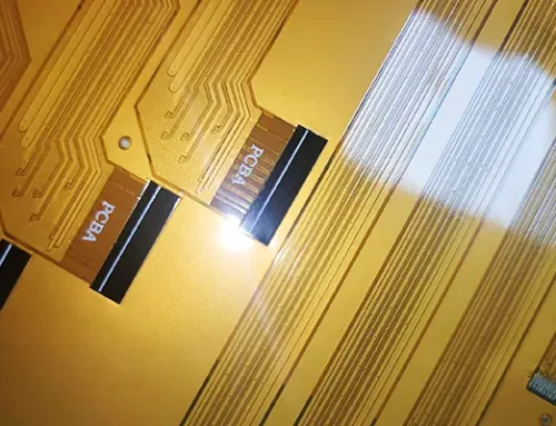
Table 1 and Figure 2 detail the process steps and outcomes.
(1) Applying PI film before burnishing, regardless of rapid pressing, carries a risk of chemical solution seepage after burnishing and is therefore unfeasible.
(2) Based on test results, combined with the material properties of PI protective film and supplier recommendations, the post-burning application process remains suitable for this material.
(3) Applying PI protective film to the flexible area effectively protects the flexible board surface and improves surface appearance issues.
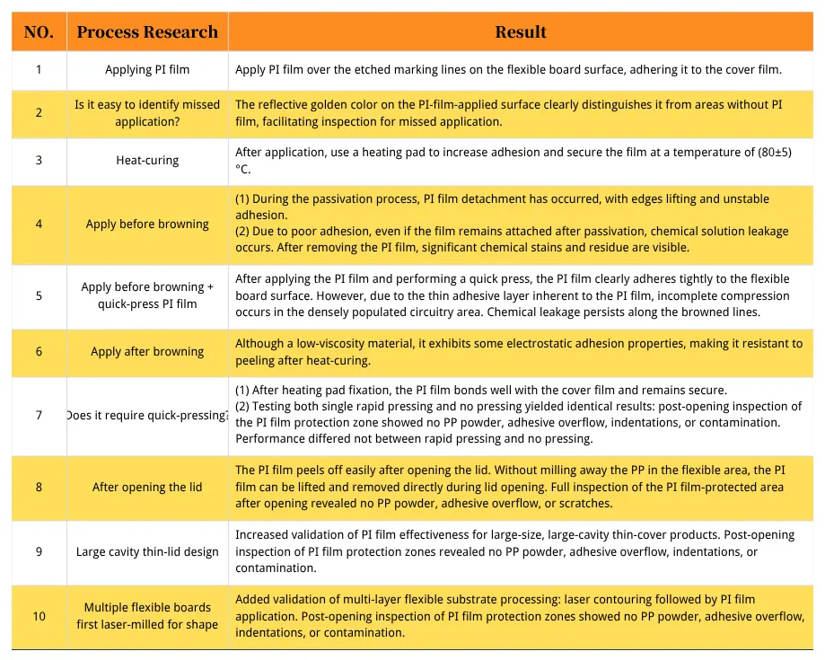
Table 1 Process Research Results
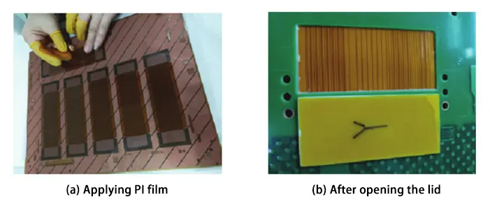
Figure 2. Applying PI and opening the lid
Material Comparison in Phase Two
Table 2 illustrates the application of the four PI films.
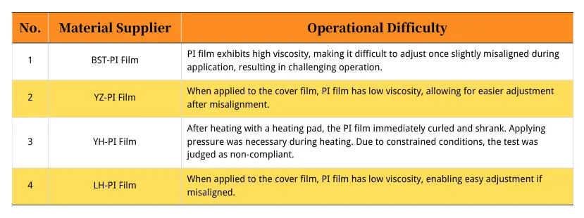
Table 2 Comparison of PI Materials
(1) BST-PI film and YH-PI film present high operational difficulty and are unsuitable for standard factory production conditions.
(2) LH-PI film and YZ-PI film demonstrate identical application performance and effectiveness. However, LH-PI film offers a price advantage. It is recommended to adopt the LH-PI film for use.
Conclusion
This study investigates the PI protective film manufacturing process and R-FPCB structure. We apply a PI protective film to the surface of the cover film in the flexible zone. This blocks PP powder and adhesive overflow and protects the flexible area from compression damage and chemical contamination.
During final lid removal, we simultaneously peel off the PI protective film. Through process flow research, we validated the findings from each stage by testing materials from different manufacturers and conducting batch technical test boards.
The research indicates that the post-browning lamination process is most suitable for PI protective films. Among the evaluated materials, LH-PI film demonstrates excellent application performance and clear cost advantages.
Batch technical trial boards validated the stable operation and maturing performance of the PI film process. It effectively improves surface appearance and resolves technical challenges such as delamination, cracking, and adhesive overflow. As a result, it significantly contributes to higher yield rates and more effective problem mitigation.
FAQ:
1. What is a Rigid-Flex Printed Circuit Board (R-FPCB)?
A Rigid-Flex PCB is a composite circuit board made by combining rigid and flexible layers into one integrated structure. It merges the mechanical stability of rigid PCBs with the design versatility of flexible circuits, allowing compact and complex 3D assemblies.
2. Why are R-FPCBs becoming more popular in modern electronics?
With the rapid advancement of PCB technology, R-FPCBs are in high demand because of their high performance and strong integration capability. They also enable compact 3D assemblies in industries such as aerospace, medical, and consumer electronics.
3. What cosmetic defects commonly occur in R-FPCB production?
During R-FPCB manufacturing, the flexible areas often suffer from defects such as pitting, resin overflow, PP powder residue, cracking, and surface contamination. These issues lead to high scrap rates.
4. What is the purpose of using a PI (polyimide) protective film in R-FPCB manufacturing?
The team applies the PI protective film to the flexible area to block PP powder, resin overflow, and chemical contamination, safeguarding the surface during lamination. This improves cosmetic quality, yield rate, and product reliability.
5. How is the PI protective film applied during the manufacturing process?
The team laminates the PI protective film onto the surface of the cover film in the flexible area. After processing and lamination, they peel it off along with the cover film, leaving a clean, defect-free flexible area.
6. What are the key steps in testing and validating the PI protective film process?
The testing involves:
Designing alignment marks for precise lamination
Defining the protective film area (0.3 mm smaller than the flexible zone)
Comparing different application timings (pre- and post-browning)
Checking film adhesion, removal performance, and visual quality
Assessing the performance of both single-layer and multi-layer flexible structures
7. Which PI film application method proved most effective?
Testing showed that post-browning lamination is the most suitable method. Applying the PI film before browning carries the risk of chemical seepage and detachment, whereas using the post-browning approach ensures both stable adhesion and clean removal.
8. What materials were compared during the PI protective film evaluation?
The team tested four PI films from different suppliers—BST-PI, YZ-PI, YH-PI, and LH-PI—evaluating their ease of application, effectiveness, and cost.
Results showed that LH-PI film and YZ-PI film performed best, with LH-PI offering a cost advantage.
9. What criteria determine acceptance of the PI protective film process?
Acceptance is based on visual inspection of the flexible area. The product must have no pitting, adhesive overflow, PP powder residue, or contamination to meet cosmetic and reliability standards.
10. What are the key outcomes of implementing the PI protective film process?
The PI protective film process effectively improves the surface appearance and yield of R-FPCBs by preventing contamination and damage. The LH-PI film, used in a post-browning lamination process, delivers excellent performance, cost efficiency, and stable production results.